Direct-current reactor type magnetizing inrush current suppressor

A technology of DC reactor and excitation inrush current, which is applied to emergency protection circuit devices, electrical components, and circuit devices used to limit overcurrent/overvoltage, etc. The effect of generating and suppressing the starting current

Inactive Publication Date: 2015-07-15
STATE GRID CORP OF CHINA +1
View PDF4 Cites 2 Cited by
  • Summary
  • Abstract
  • Description
  • Claims
  • Application Information

AI Technical Summary

Problems solved by technology

These technical solutions are good for suppressing the starting current of the motor, but at the same time, they will have a certain impact on the normal operation of the motor

Method used


Image

  • Direct-current reactor type magnetizing inrush current suppressor
  • Direct-current reactor type magnetizing inrush current suppressor
  • Direct-current reactor type magnetizing inrush current suppressor

Examples


Embodiment Construction

[0014] Embodiments of the present invention will be described in further detail below in conjunction with the accompanying drawings.

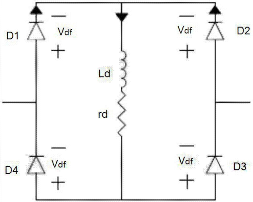
[0015] A DC reactor type excitation inrush suppressor, such as figure 1 As shown, it includes four diodes D1, D2, D3, D4, inductor Ld, and resistor rd. The anode of diode D1 and the cathode of diode D4 are commonly connected to the AC voltage source, and the cathode of diode D1 is connected to the cathode of diode D2. The anode of the diode D4 is connected to the anode of the diode D3, the anode of the diode D2 and the cathode of the diode D3 are connected to the generator, the cathode of the diode D1 and the cathode of the diode D2 are also connected to the inductance Ld and the resistor rd connected in series, The other ends of the inductance Ld and the resistor rd connected in series are connected to the anode of the diode D4 and the anode of the diode D3.

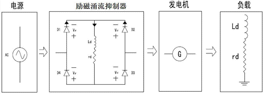
[0016] An application system of the DC reactor type excitation inrush current suppr...


PUM


Abstract

The invention relates to a direct-current reactor type magnetizing inrush current suppressor. The magnetizing inrush current suppressor is characterized by comprising four diodes, an inductor and a resistor, wherein the positive pole of the diode D1 and the negative pole of the diode D4 are connected with an alternating-current voltage source, the negative pole of the diode D1 is connected with that of the diode D2, the positive pole of the diode D4 is connected with that of the diode D3, the positive pole of the diode D2 and the negative pole of the diode D3 are connected with a generator, the negative pole of the diode D1 and that of the diode D2 are also connected with one ends of the inductor Ld and the resistor rd which are connected together in series, and the other ends of the inductor Ld and the resistor rd which are connected together in series are connected with the positive pole of the diode D4 and that of the diode D3. The magnetizing inrush current suppressor disclosed by the invention is directly accessed into an electric network, at the moment of electrifying, the resistor and the inductor are used for suppressing the mutation of a current, so that the generation of the starting current can be effectively suppressed; during stable operation, the normal running of the generator is not influenced, and besides, the mass production is convenient; the magnetizing inrush current suppressor has a favorable application prospect.

Description

technical field [0001] The invention belongs to the technical field of motor starting current suppression, in particular to a DC reactor type excitation inrush current suppressor. Background technique [0002] The inrush current when the motor starts is the amount of current change from the moment the motor or inductive load is energized to the short period of stable operation. This current is generally 4-7 times the rated current. According to national regulations, for the safety of the line operation and the normal operation of other electrical equipment, high-power engines must be equipped with starting equipment to reduce the starting current. The common starting methods of AC motors include direct starting, series resistance starting, self-coupling transformer starting, star-delta decompression starting and inverter starting to reduce the impact on the power grid. These technical solutions are good for suppressing the starting current of the motor, but at the same time...

Claims


Application Information

Patent Timeline
Patent Type & Authority Applications(China)
IPC IPC(8): H02H9/02
Inventor 何金宋晓博王晓光杨磊
Owner STATE GRID CORP OF CHINA
Why Eureka
Try Eureka