Eureka AIR delivers breakthrough ideas for toughest innovation challenges, trusted by R&D personnel around the world.

Special automatic fire extinguishing device for battery box

An automatic fire extinguishing and battery box technology, applied in fire rescue and other directions, can solve the problems of power battery or capacitor explosion and combustion, unsatisfactory fire extinguishing effect, endangering the lives of people in the vehicle, etc., to improve the utilization rate and respond quickly. , control flexible effects

Inactive Publication Date: 2015-07-22
CNBCC AUTOMOBILE SPARE PART XIAMEN
View PDF7 Cites 33 Cited by
  • Summary
  • Abstract
  • Description
  • Claims
  • Application Information

AI Technical Summary

Problems solved by technology

When short-circuit thermal runaway, high temperature, external force extrusion, puncture, etc. occur inside the power battery or supercapacitor, it is easy to cause thermal expansion of the power battery or capacitor, resulting in explosion and combustion
Once a fire accident occurs inside the battery box of a new energy bus, if the fire is not effectively extinguished in time, it will endanger the lives of the people on board and cause huge losses to the personal safety and property of the people on board.
At present, although there are many fire extinguishing devices for extinguishing power batteries in the prior art, most of them are designed for extinguishing a single battery box, which is not practical for new energy buses with multiple battery boxes.
In addition, the fire extinguishing device for the power battery of the prior art, in the actual use process, the fire extinguishing effect is not satisfactory

Method used


Image

  • Special automatic fire extinguishing device for battery box
  • Special automatic fire extinguishing device for battery box
  • Special automatic fire extinguishing device for battery box

Examples


Embodiment Construction

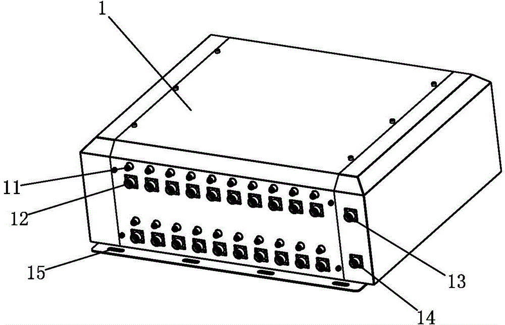
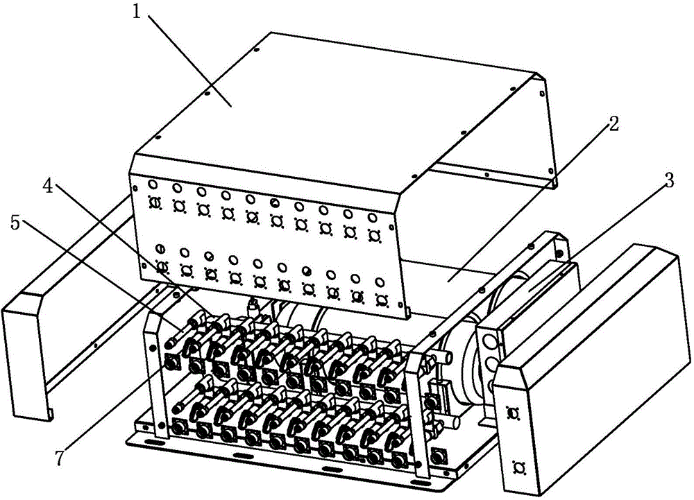
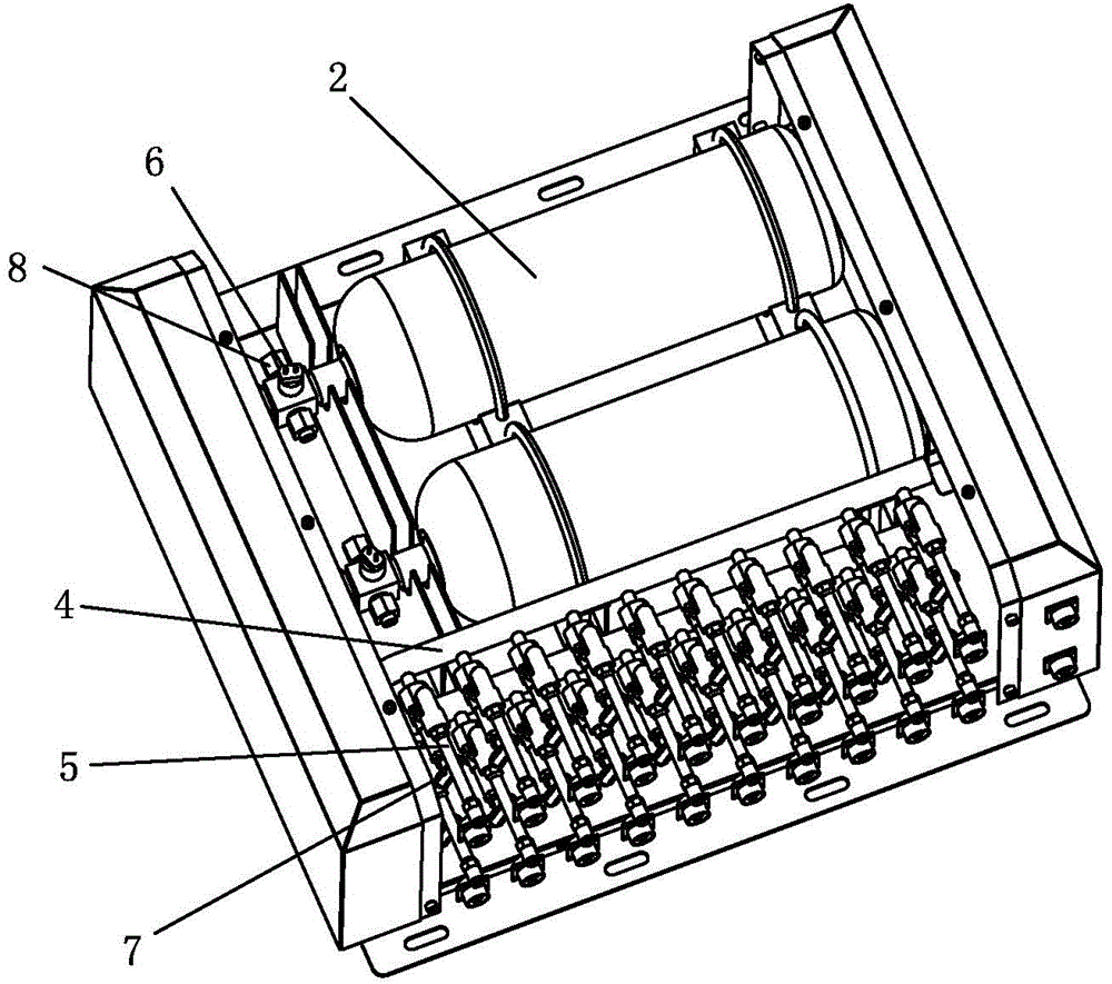
[0029] Examples, see Figure 1-Figure 3 As shown, a special automatic fire extinguishing device for a battery box of the present invention is used to extinguish the fire of the power battery or supercapacitor in the battery box of the vehicle (in this embodiment, take a new energy bus as an example), and it includes:

[0030] A plurality of aspirating fire detectors (not shown in the figure) are used to detect whether there is fire in each battery box. During installation, each battery box of the bus is equipped with at least one of the aspirating fire detectors. Specifically, The aspirating fire detector can collect the gas released when the power battery or super capacitor is at high temperature and the smoke generated when the fire occurs;

[0031] At least two fire extinguishing agent containers 2 are equipped with fire extinguishing agent and are pressure storage type. Specifically, the fire extinguishing agent can be a mixed gas fire extinguishing agent and / or an ultrafi...


PUM


Abstract

The invention discloses a special automatic fire extinguishing device for a battery box. The special automatic fire extinguishing device comprises a plurality of air suction type fire disaster detectors, at least two fire extinguishing agent containers, and a controller, wherein the air suction type fire disaster detectors are used for detecting whether the interior of each battery box catches a fire or not; the fire extinguishing agent output opening of each fire extinguishing agent container is connected with a fire extinguishing agent conveying pipe network; each fire extinguishing agent conveying pipe network comprises a main pipeline and a plurality of branch pipelines which are connected with the main pipeline; each battery box of a coach is connected with at least one branch pipeline; a first valve is mounted at the fire extinguishing agent output opening of each main pipeline or each fire extinguishing agent container; a second valve is mounted on each branch pipeline; the controller is connected with the air suction type fire disaster detectors, the first valves and the second valves, and controls whether each of the first valves and the second valves is opened or closed according to detecting results of the air suction type fire disaster detectors. According to the special automatic fire extinguishing device for the battery box, each battery box of the coach can be effectively protected one by one; the personal and property safety of passengers on the coach caused by fire spreading because a new energy coach catches a fire can be prevented.

Description

technical field [0001] The invention relates to a fire extinguishing device, in particular to a special automatic fire extinguishing device for a battery box. Background technique [0002] At present, the power equipment of new energy buses is mainly power batteries or super capacitors, and a new energy bus is generally installed with multiple battery boxes, and each battery box is equipped with power batteries or super capacitors. When short-circuit thermal runaway, high temperature, external force extrusion, puncture, etc. occur inside the power battery or supercapacitor, it is easy to cause thermal expansion of the power battery or capacitor, resulting in explosion and combustion. Once a fire accident occurs inside the battery box of a new energy bus, if the effective fire extinguishing is not implemented in time, it will endanger the lives of the people on board and cause huge losses to the personal safety and property of the people on board. At present, although there ...

Claims


Application Information

Patent Timeline
IPC IPC(8): A62C3/16A62C37/00
CPCA62C3/16A62C37/04
Inventor 洪伟艺刘文辉陈庚强吴添林华伟
Owner CNBCC AUTOMOBILE SPARE PART XIAMEN
Why Eureka
Eureka Blog
Learn More