
Numerical control boring machine for machining thrust surface of engine cylinder body

An engine cylinder block and thrust surface technology, applied in the field of CNC boring machines, can solve the problems affecting the overall performance of the engine, poor machining accuracy and roughness compensability of the two thrust surfaces, etc., to achieve good operability, improve product quality and The effect of working efficiency and shortening auxiliary time

Inactive Publication Date: 2015-07-22
XIANGYANG NEW TORCH CNC MACHINE TOOL
View PDF0 Cites 1 Cited by
  • Summary
  • Abstract
  • Description
  • Claims
  • Application Information

AI Technical Summary

Problems solved by technology

[0002] In the existing technology, most of the processing of the thrust surface of the traditional engine block adopts the form milling method, resulting in poor machining accuracy and roughness compensability of the two thrust surfaces, which greatly affects the overall performance of the engine

Method used

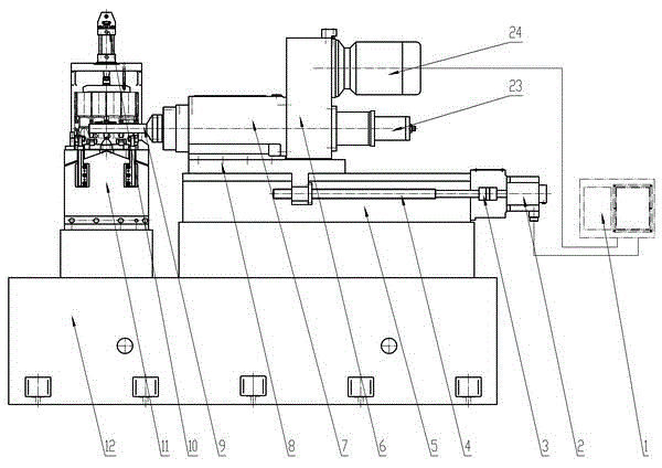
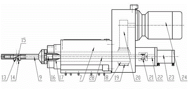
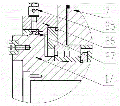

Image

  • Numerical control boring machine for machining thrust surface of engine cylinder body
  • Numerical control boring machine for machining thrust surface of engine cylinder body
  • Numerical control boring machine for machining thrust surface of engine cylinder body

Examples


Embodiment Construction

[0010] like figure 1 , figure 2 , image 3 As shown, the electrical system 1 of the present invention is connected with the servo motor 2 and the motor 24; The ball screw pair 4 in the slide seat 5 is connected through the coupling 3, the ball screw pair 4 is connected with the slide plate 8 through threads, the slide plate 8 is slidingly matched with the guide rail on the slide seat 5, and the slide plate 8 is in the position of the servo motor 2. Driven to realize lateral movement; the boring head 7 is fixed on the slide plate 8, the belt pulley 19 of the transmission device 6 is connected with the motor 24 on the transmission device 6 through the belt 20, and the belt pulley 19 is connected with the motor of the boring head 7 through the spline sleeve 18 The main shaft 17 is connected, the boring bar 9 is connected with the main shaft 17, the motor 24 drives the boring bar 9 to rotate through the main shaft 17; the push rod cylinder 23 is fixed on the transmission device...


PUM


Abstract

The invention discloses a numerical control boring machine for machining a thrust surface of an engine cylinder body, and relates to the field of mechanical machining equipment. An electrical system is connected with a servo motor and a motor, and a sliding seat and a hydraulic clamp are mounted on a machine tool base; the servo motor is connected with a ball screw assembly through a coupler, and the ball screw assembly is connected with a sliding plate in a threaded manner; and the sliding plate is matched with a guide rail on the sliding seat in a sliding manner. A boring head is fixed to the sliding plate, and a belt wheel is connected with the motor through the belt and is connected with a spindle through a spline sleeve; the boring rod is connected with the spindle; a pushing rod oil cylinder is fixed to a transmission device, and a piston rod of the pushing rod oil cylinder is connected with a spindle pushing rod through a rotating joint; the spindle pushing rod is connected with a pushing rod, and the pushing rod is provided with an inclined face boss; and the inclined face boss is matched with an inclined face groove of a tool apron sliding block, and a tool is arranged on the tool apron sliding block. The numerical control boring machine is simple, compact and reasonable in structure, high in starting speed, easy to operate, high in reliability and capable of achieving machining size compensation; and auxiliary time in the machining process is greatly shortened, and the product quality and the working efficiency are high.

Description

technical field [0001] The invention relates to the technical field of mechanical processing equipment, in particular to a numerically controlled boring machine for processing thrust surfaces of engine cylinder blocks. Background technique [0002] In the prior art, the machining of the thrust surface of the traditional engine block mostly adopts the form milling method, resulting in poor machining accuracy and roughness compensability of the two thrust surfaces, which greatly affects the overall performance of the engine. Contents of the invention [0003] In order to overcome the deficiencies of the prior art, the object of the present invention is to provide a numerically controlled boring machine for machining the thrust surface of the engine cylinder, so as to achieve the purpose of compensable machining accuracy and simple adjustment of the thrust surface of the engine cylinder. [0004] In order to achieve the above object, the present invention includes an electric...

Claims


Application Information

Patent Timeline
Patent Type & Authority Applications(China)
IPC IPC(8): B23B41/00
CPCB23B41/00B23B2215/24
Inventor 赵进冬
Owner XIANGYANG NEW TORCH CNC MACHINE TOOL
Learn More