High temperature pellet waste heat recovery heat utilization device

A pellet, high temperature technology, applied in the field of high temperature pellet waste heat recovery heat utilization device, can solve the problems of uneven heat exchange, small gas pellet heat exchange area, low air preheating temperature, etc., and achieves simple structure and significant energy saving benefits. , the effect of simple configuration of auxiliary equipment

Inactive Publication Date: 2016-10-05
ZHUZHOU FLASHLIGHT IND FURNACE
View PDF7 Cites 0 Cited by
  • Summary
  • Abstract
  • Description
  • Claims
  • Application Information

AI Technical Summary

Problems solved by technology

[0005] In order to overcome the small heat transfer area and uneven heat transfer of gas particles in traditional fixed bed heat exchangers, or the need for high-pressure air and the existence of side walls, temperature fields and funnel effects, moving bed heat exchangers are connected in parallel to cool kiln slag, and the air preheating temperature is not stable. Higher disadvantages, the present invention discloses a kind of integrated "Venturi nozzle air-particle two-phase flash heat transfer, granular material layered dispersion-spray heat transfer, heat pipe heat exchanger series heat transfer" and other principles, with "high-temperature granular material cooling To 100 ℃ and below, preheating the air to 100 ℃ ~ 150 ℃ lower than the pellet inlet temperature" and other technical advantages of high-temperature pellet waste heat recovery heat utilization device

Method used


Image

  • High temperature pellet waste heat recovery heat utilization device
  • High temperature pellet waste heat recovery heat utilization device

Examples


Embodiment Construction

[0010] The invention will be further described below in conjunction with the accompanying drawings.

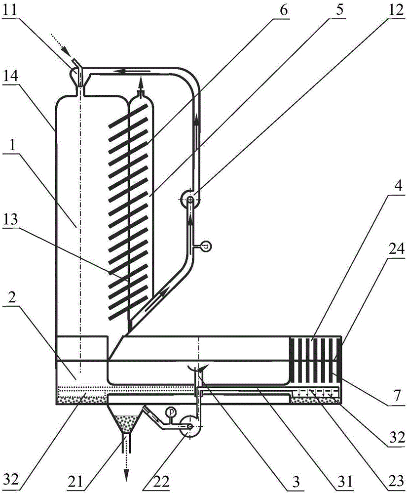
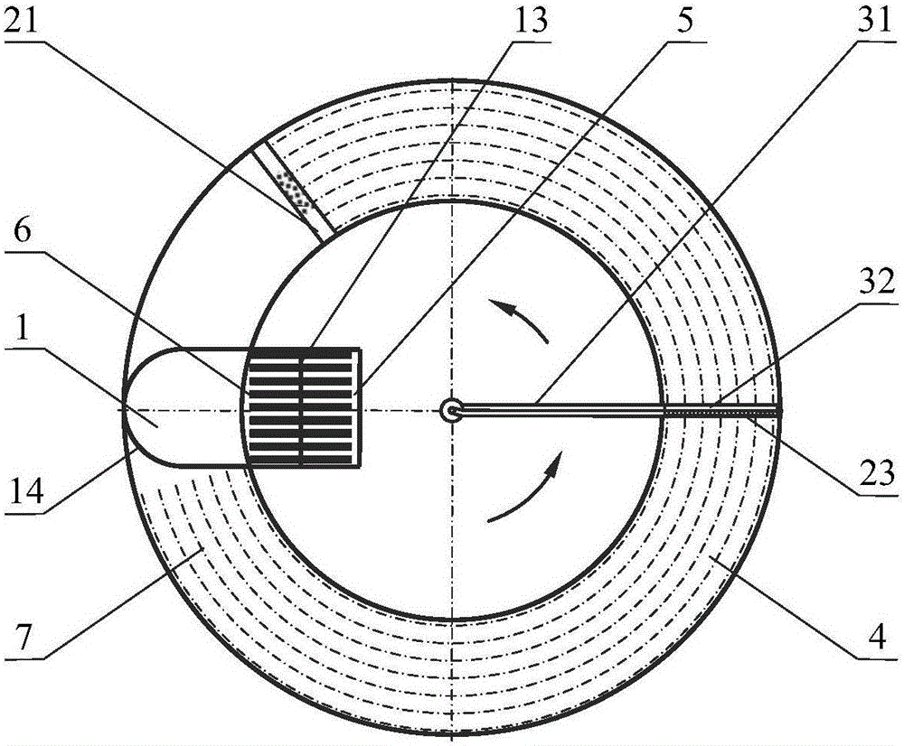
[0011] as attached figure 1 And attached figure 2 As shown, the high-temperature pellet waste heat recovery heat utilization device mainly includes a flash cooling chamber 1, a slow cooling chamber 2, a pellet dispersing mechanism 3, a preheating chamber 4, a reheating chamber 5, a high-temperature heat pipe bundle 6 and a medium-temperature heat pipe bundle 7.

[0012] The flash cooling chamber 1 includes a Venturi nozzle 11 and a high temperature fan 12 . The flash cooling chamber 1 is in the form of a composite body composed of vertically arranged semi-columns and vertically arranged square columns. One side of the square column and the side plane of the semi-cylindrical completely overlap. The exhaust port, the exhaust port is connected with the suction port of the high-temperature fan 12 outside the flash cooling chamber 1 through the suction pipe of the high-temperat...


PUM


Abstract

The invention discloses a waste heat recovery heat utilization device for high-temperature particle materials. The waste heat recovery heat utilization device comprises a flash cooling chamber, a slow cooling chamber, a preheating chamber, a reheating chamber and heat tube bundles, wherein a high-temperature draught fan is connected with an exhaust opening in the bottom of the side face of the flash cooling chamber and an air inlet of a Venturi nozzle of the top face of the flash cooling chamber, the slow cooling chamber is cylindrical, a temperature-resistance draught fan is connected with an exhaust opening of the slow cooling chamber and a jetting pipe, the jetting pipe is tightly attached to the rear back face of a bulk cargo plate capable of rotating by 360 degrees in an annular channel of the slow cooling chamber, and the surface of the particle materials is cooled by jetting flow after a particle material pile is scattered by the bulk cargo plate. The bottom face of a splat cooling chamber and the top face of the slow cooling chamber share the same surface. The middle temperature heat tube bundle perpendicularly penetrates through the preheating chamber and the slow cooling chamber, the extension lengths of the middle temperature heat tube bundle at the two ends are the same, the high temperature heat tube bundle obliquely penetrates through the reheating chamber and the flash cooling chamber, and the extension lengths of the high temperature heat tube bundle at the two ends are the same. The waste heat recovery heat utilization device can be used in high-temperature particle material waste heat recovery heat utilization places where waste heat quantity is small or fluctuates. By the adoption of the device, clean and high-quality high temperature air resources can be generated, the particle materials can be cooled to be at the temperature below 100 DEG C, the air is preheated to be at the temperature of 800-900 DEG C, the temperature efficiency is higher than 85%, and the waste heat recovery efficiency is higher than 70%.

Description

technical field [0001] The invention belongs to the field of industrial energy saving, and relates to a high-temperature granular material waste heat recovery heat utilization device suitable for use in high-temperature granular materials or slag materials, such as high-temperature cement clinker, high-temperature roasted sand, and high-temperature leaching slag waste heat recovery heat utilization sites of zinc volatilization kilns . Background technique [0002] Waste heat recovery and utilization project is the second largest key energy-saving project in my country during the "Twelfth Five-Year Plan" period. According to incomplete statistics, the total amount of available industrial waste heat energy in my country is about 740×10 12 kilojoules / year. Solid waste heat accounts for about 30%. The vast majority of solid waste heat with large waste heat, constant waste heat quantity and temperature, concentrated waste heat resources, and low dust and corrosive substances ha...

Claims


Application Information

Patent Timeline
Patent Type & Authority Patents(China)
IPC IPC(8): F27D15/02F27D17/00
CPCY02P80/15
Inventor 鲁志昂熊泽庆裴石磊艾元方
Owner ZHUZHOU FLASHLIGHT IND FURNACE
Why Eureka
Try Eureka