Acoustic wave sensing measurement device based on optical fiber sagnac interferometer

A measuring device, acoustic wave sensing technology, applied in the direction of measuring device, measuring ultrasonic/sonic wave/infrasonic wave, instrument, etc., can solve the problems of difficult signal demodulation, changing output optical signal, affecting FP cavity length, etc., to achieve improvement The effects of detecting sensitivity, reducing the influence of system work, and improving accuracy

Active Publication Date: 2015-07-22
HUAZHONG UNIV OF SCI & TECH
View PDF4 Cites 12 Cited by
  • Summary
  • Abstract
  • Description
  • Claims
  • Application Information

AI Technical Summary

Problems solved by technology

[0003] The optical fiber acoustic wave sensor based on the Fabry-Perot interferometer in the prior art is to cause the membrane vibration of the Fabry-Perot cavity (Fabry-Perot cavity, FP cavity) by the sound wave, thereby affecting the cavity of the FP cavity Long, and then change its output optical signal, the sensor head of this scheme is more complicated to manufacture, and the signal demodulation is more difficult
[0004] In the prior art, the optical fiber acoustic wave sensing structure based on the Mach-Zehnder Interferometer (MZI) uses one arm of the MZI as a reference, and the bare fiber on the other arm as the sensing arm. Under the influence of the deformation, the acoustic frequency and the acoustic pressure are measured separately. This structure requires two optical fiber couplers, and the optical fiber needs to be properly wound in the sensing arm of the MZI. The system structure is relatively complicated.

Method used


Image

  • Acoustic wave sensing measurement device based on optical fiber sagnac interferometer
  • Acoustic wave sensing measurement device based on optical fiber sagnac interferometer
  • Acoustic wave sensing measurement device based on optical fiber sagnac interferometer

Examples


Embodiment Construction

[0028] In order to make the object, technical solution and advantages of the present invention clearer, the present invention will be further described in detail below in conjunction with the accompanying drawings and embodiments. It should be understood that the specific embodiments described here are only used to explain the present invention, not to limit the present invention. In addition, the technical features involved in the various embodiments of the present invention described below can be combined with each other as long as they do not constitute a conflict with each other.

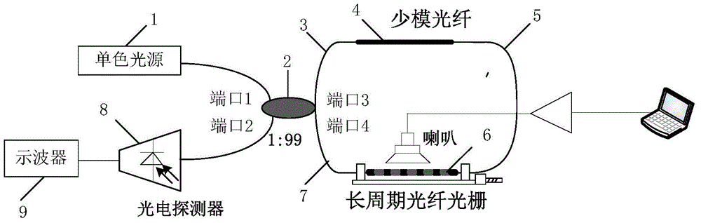
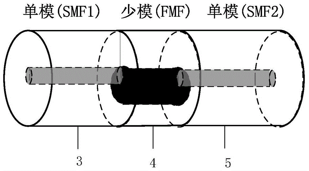
[0029] The acoustic wave sensing and measuring device based on the optical fiber Sagnac interferometer provided by the present invention includes a monochromatic light source, a fiber coupler, a first single-mode fiber, a few-mode fiber, a second single-mode fiber, a long-period fiber grating, and a second single-mode fiber. Three single-mode fibers and photodetectors;

[0030] Wherein, the fir...


PUM


Abstract

The invention discloses an acoustic wave sensing measurement device based on an optical fiber sagnac interferometer. The acoustic wave sensing measurement device comprises a single-color light source, an optical fiber coupler, a first single-mode optical fiber, a few-mode optical fiber, a second single-mode optical fiber, a long-period optical fiber grating, a third single-mode optical fiber, a photoelectric detector and an oscilloscope, the first single-mode optical fiber, the few-mode optical fiber, the second single-mode optical fiber, the long-period optical fiber grating and the third single-mode optical fiber which are arranged between a third end and a fourth end of the optical fiber coupler are sequentially connected to form a sagnac closed-loop structure, and the long-period optical fiber grating and the few-mode optical fiber realize cascade connection in a sagnac closed-loop. When outside acoustic wave acts on the long-period optical fiber grating, curvature of the outside acoustic wave is modulated by acoustic frequency signals, drift of resonant wavelength at loss peak of the outside acoustic wave is caused, and light power change at a wavelength position corresponding to a bevel edge of the loss peak is analyzed by means of bevel edge demodulation to demodulate to-be-measured acoustic wave signals so as to realize sensing measurement of the acoustic wave signals.

Description

technical field [0001] The invention belongs to the technical field of optical fiber acoustic wave measurement, and in particular relates to an acoustic wave sensing and measuring device based on an optical fiber Sagnac interferometer. Background technique [0002] In recent years, due to the frequent occurrence of natural disasters, fiber optic acoustic wave sensors have gradually entered people's field of vision, and have important applications in hydrophones, earthquake prediction, oil exploration, safety detection, military and other fields. Optical fiber acoustic wave sensor mainly realizes acoustic wave detection by detecting sound pressure. Compared with ordinary electrical acoustic wave sensor, optical fiber sensor has extremely strong anti-interference ability, can be used in strong electromagnetic and strong radiation occasions, and has extremely high detection sensitivity. The system Large response range and corrosion resistance. [0003] The optical fiber acoust...

Claims


Application Information

Patent Timeline
Patent Type & Authority Applications(China)
IPC IPC(8): G01H9/00
Inventor 鲁平傅鑫陈静刘德明
Owner HUAZHONG UNIV OF SCI & TECH
Why Eureka
Try Eureka