Refrigerating agent filling and recovering system and refrigerating agent filling and recovering method for vehicle air conditioner test system

A technology for testing systems and vehicle air conditioners, applied in refrigerants, refrigerators, refrigeration components, etc., can solve problems such as difficult control, low pressure in the liquid storage tank, and inability to refill normally, avoiding maintenance and replacement, and reducing costs. and noise, to achieve the effect of reuse

Active Publication Date: 2015-07-29
上海佐竹冷热控制技术有限公司
View PDF5 Cites 13 Cited by
  • Summary
  • Abstract
  • Description
  • Claims
  • Application Information

AI Technical Summary

Problems solved by technology

[0008] figure 2 The unit shown uses the compressor to recover the refrigerant, which not only increases the cost, but also if the compressor contains lubricating oil, it may also seep into the lubricating oil in the compressor
In addition, the liquid storage tank is placed in a normal temperature environment and does not have a temperature control function. When the external ambient temperature is low, the pressure in the liquid storage tank may be low, so that during the filling process, due to The pressure in the liquid storage tank is balanced with the pressure in the air conditioning system, which causes the problem that it cannot be filled normally
In addition, the filling accuracy of the device is low, generally ±5g
[0009] To sum up, the filling recovery device using a plunger pump or compressor has low filling accuracy, is difficult to control, and has high equipment costs. At the same time, the moving parts are easily damaged, which reduces the reliability of the system and generates relatively large noise.

Method used


Image

  • Refrigerating agent filling and recovering system and refrigerating agent filling and recovering method for vehicle air conditioner test system
  • Refrigerating agent filling and recovering system and refrigerating agent filling and recovering method for vehicle air conditioner test system
  • Refrigerating agent filling and recovering system and refrigerating agent filling and recovering method for vehicle air conditioner test system

Examples


Embodiment Construction

[0038] The present invention will be further described in detail below in conjunction with the accompanying drawings and specific embodiments.

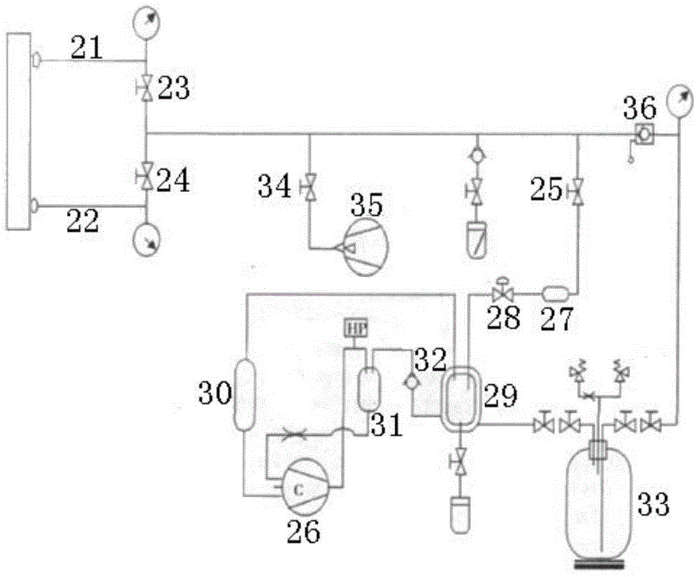
[0039] The refrigerant filling recovery system used for the vehicle air-conditioning test system provided by the present invention, such as Figure 4 As shown, it includes a liquid storage tank 41, a vacuum pump 42, a vacuum gauge 43, a first pipeline 59 connected to the low-pressure side of the air conditioner and a filling terminal, a second pipeline 60 connected to the high-pressure side of the air conditioner and a recovery terminal, and in addition Also include filling tank 44, recovery tank 45, temperature control box 46,47, heater, cooler, weighing device 49 and control unit (not shown in the figure), wherein:

[0040] The filling tank 44 is located in a first temperature control box 46, which is connected to the liquid storage tank 41 through a refrigerant replenishment valve 50, and is connected to the first pipeline 59 throu...


PUM


Abstract

The invention discloses a refrigerating agent filling and recovering system and a refrigerating agent filling and recovering method for a vehicle air conditioner test system. The refrigerating agent filling and recovering system comprises a liquid storage tank, a vacuum pump, a vacuum gauge, a first pipeline, a second pipeline, a filling tank, a recovering tank, a temperature control tank, a heater, a cooler, a weighing device and a control unit, wherein the filling tank which is arranged in a first temperature control box is connected with the liquid storage tank by virtue of a refrigerating agent replenishing valve and connected with the first pipeline by virtue of a filling valve; the recovering tank which is arranged in a second temperature control box is connected with a second pipeline by virtue of a recovering valve; the heater and the cooler are respectively used for controlling the temperature of the first temperature control box and the second temperature control box, and the two temperature control boxes are arranged on the weighing device; a low pressure pipeline and the second pipeline are respectively connected with the vacuum pump by virtue of a low-pressure vacuum valve and a high-pressure vacuum valve, a communication valve is arranged between the filling tank and the recovering tank, and one of the filling tank and the recovering tank is connected with the vacuum pump by virtue of a filling recovering vacuum valve; the control unit is connected with the weighing device, the heater, the cooler, the vacuum gauge and all valves. By adopting the system and the method, quantitative filling and temperature control can be accurately realized, and the reutilization of the refrigerating agent can be realized by switching the state of the temperature control boxes.

Description

technical field [0001] The invention relates to the technical field of air-conditioning and refrigeration, in particular to a refrigerant filling and recovery system and method for a vehicle air-conditioning test system. Background technique [0002] At present, in the filling and recycling field of automotive air-conditioning refrigerants, most of them use pump filling and compressor recovery. [0003] figure 1 It is a schematic diagram of a common device for filling refrigerant through a plunger pump, which includes a plunger pump 11, a vacuum pump 12, sensors (including a pressure sensor 13 and a vacuum sensor 14), a flow meter 15, a fluid control valve, etc., The whole process of vacuum quantitative filling of refrigerant mainly includes several process sequences of vacuuming, pressure maintaining and leak detection, secondary vacuuming, and filling. [0004] First, use the vacuum pump 12 to discharge the air in the automobile air conditioning system, and use the vacuu...

Claims


Application Information

Patent Timeline
IPC IPC(8): F25B45/00
CPCF25B45/00F25B2345/005
Inventor 张鹏吴晓菁
Owner 上海佐竹冷热控制技术有限公司
Why Eureka
Try Eureka