Dual-heating interior spiral drum type biomass material dryer

An internal spiral and drum type technology, applied in the field of biomass energy utilization, can solve the problems of extending the length of the drying cylinder, high speed of hot air flow, and low drying efficiency, and achieve the effects of improving drying efficiency, reducing heat loss, and reducing self-weight

Inactive Publication Date: 2015-07-29
周杨一帆
View PDF0 Cites 10 Cited by
  • Summary
  • Abstract
  • Description
  • Claims
  • Application Information

AI Technical Summary

Problems solved by technology

However, there are the following defects: 1. The hot air temperature needs to be high, otherwise the drying purpose cannot be achieved, or the length of the drying cylinder needs to be extended, and the drying efficiency is low and the effect is not good; 2. In order to achieve the effect of quickly dissipating the water vapor, the hot air flow The higher the speed, the higher the hot air is directly discharged, resulting in a lot of waste of capacity

Method used


Image

  • Dual-heating interior spiral drum type biomass material dryer
  • Dual-heating interior spiral drum type biomass material dryer

Examples


Embodiment 1

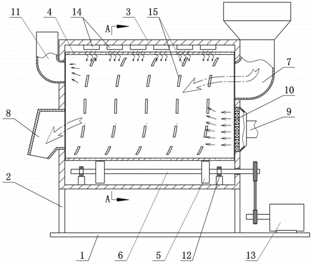
[0013] Embodiment 1: The first kind of double heating internal spiral drum type biomass material dryer, see figure 1 with figure 2 , the lower side of the bracket is fixed on the base 1, and a sealed box 3 is fixed on the bracket 2.

[0014] A heating device is provided in the sealed box 3 as a main heating source. The fixed sealing box 3 is conducive to installing the heating device, and the heating device has various weights, such as electric heating tubes and other parts that can be arranged on the bottom or both sides or top of the sealing box.

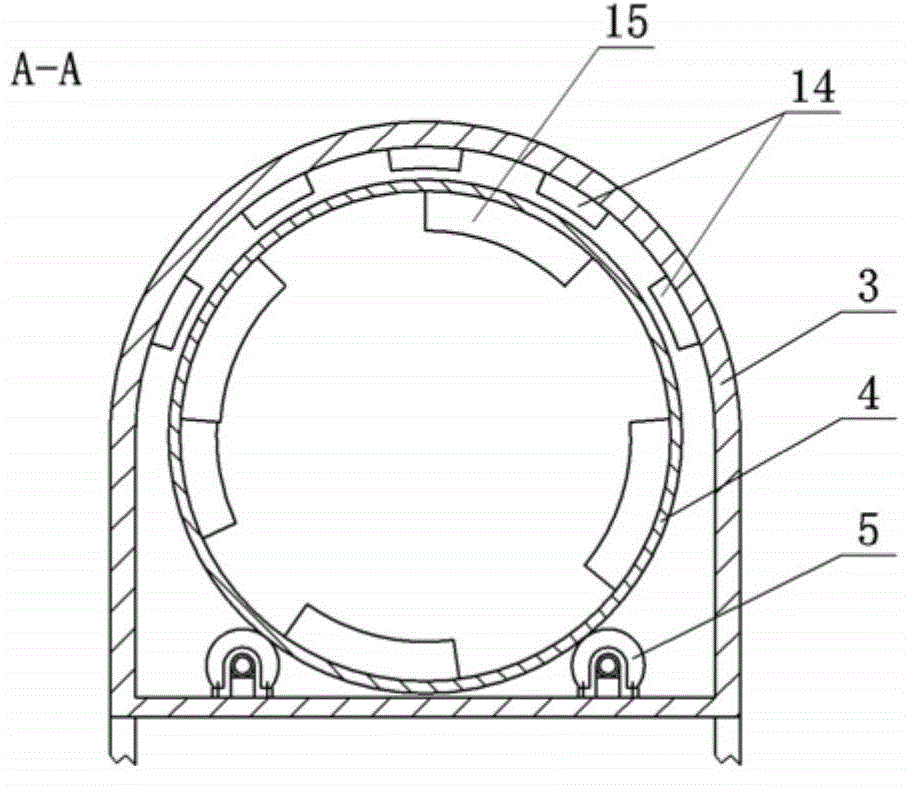
[0015] A roller 4 is installed in the sealing box 3, and the roller 4 is supported by the roller 5 and driven by the roller. The two ends of the roller 4 are open, but they slide with the inner wall of the sealing box 3. side walls at both ends. The specific structure is given by figure 2 , a pair of transmission shafts 6 parallel to the axial direction are arranged at the bottom of the sealing box 3, and each transmission s...

Embodiment 2

[0019] Embodiment 2: The second kind of double heating internal spiral drum type biomass material dryer, see figure 1 with figure 2 , the content is basically the same as that of Example 1, and the similarities will not be repeated. The difference is that the heating device is a microwave heating device 14 located at the top in the sealed box. The whole sealed box is equivalent to a microwave oven. Devices to prevent microwave leakage are installed near the feed inlet and outlet. For example, annular water chambers are respectively provided near the feed inlet and outlet.

Embodiment 3

[0020] Embodiment 3: The second kind of double heating internal spiral drum type biomass material dryer, see figure 1 with figure 2 , the content is basically the same as that of Example 1, the difference is that, on the basis of Example 1, the hot air inlet pipe 9 is set as a tapered enlarged section, and an air diffuser 10 is set in the tapered enlarged section. The air diffuser 10 is a panel with a plurality of ventilation holes evenly distributed in the middle.


PUM


Abstract

The invention discloses a dual-heating interior spiral drum type biomass material dryer. A sealing tank is fixedly arranged on a bracket, wherein a heating device is arranged inside the sealing tank and used as a main heating source; a drum, a carrier roller and a transmission mechanism are arranged in the sealing tank; the carrier roller and the transmission mechanism are used for supporting the drum; a feeding hopper and a hot air intake pipe are arranged at one end of the sealing tank; the hot air intake pipe is used as an auxiliary heating source; a discharge outlet and a damp air exhaust opening are formed in the other end. The dual-heating interior spiral drum type biomass material dryer is capable of lowering heat energy of a hot air channel, thus the hot air channel is mainly used for accelerating the flowing of water vapor in the drum and is not utilized as a main heat source; improvement and storage of heat energy in the drum are facilitated, thus high-temperature hot air flow is prevented from being directly discharged, drying efficiency is improved and loss of heat energy is reduced.

Description

technical field [0001] The invention relates to the technical field of biomass energy utilization, in particular to a double-heating internal spiral drum type biomass material dryer. Background technique [0002] Existing material dryers used in the field of biomass energy recovery and reuse usually adopt an external heating method, such as using hot air to heat the inside of the drum while blowing away the humid air to achieve the purpose of drying. However, there are the following defects: 1. The hot air temperature needs to be high, otherwise the drying purpose cannot be achieved, or the length of the drying cylinder needs to be extended, and the drying efficiency is low and the effect is not good; 2. In order to achieve the effect of quickly dissipating the water vapor, the hot air flow The higher the speed, the higher the hot air is directly discharged, resulting in a lot of waste of capacity. If an internal heat source is provided for the drum, a series of technical p...

Claims


Application Information

Patent Timeline
Patent Type & Authority Applications(China)
IPC IPC(8): F26B11/06F26B21/00F26B23/08F26B23/04
Inventor 周杨一帆
Owner 周杨一帆
Why Eureka
Try Eureka