
Fuel cell stack manifold with ejector function

A fuel cell stack and fuel cell technology, applied in the direction of fuel cells, fuel cell parts, power system fuel cells, etc., can solve the problems of recirculation system volume and weight increase, complex structure, etc., to reduce manufacturing costs and Effects of weight, reduction of manufacturing cost, and simplification of the manufacturing process

Active Publication Date: 2015-07-29
HYUNDAI MOTOR CO LTD
View PDF4 Cites 5 Cited by
  • Summary
  • Abstract
  • Description
  • Claims
  • Application Information

AI Technical Summary

Problems solved by technology

[0014] However, these conventional recirculation systems suffer from increased size, weight, and complexity due to the channels and components required to mount the pump mechanism to the stack manifold

Method used


Image

  • Fuel cell stack manifold with ejector function
  • Fuel cell stack manifold with ejector function
  • Fuel cell stack manifold with ejector function

Examples


Embodiment

[0049] Hereinafter, the present invention will be described in more detail with reference to the accompanying drawings so that those skilled in the art can more easily implement the present invention.

[0050] The present invention will be described in detail below with reference to the accompanying drawings.

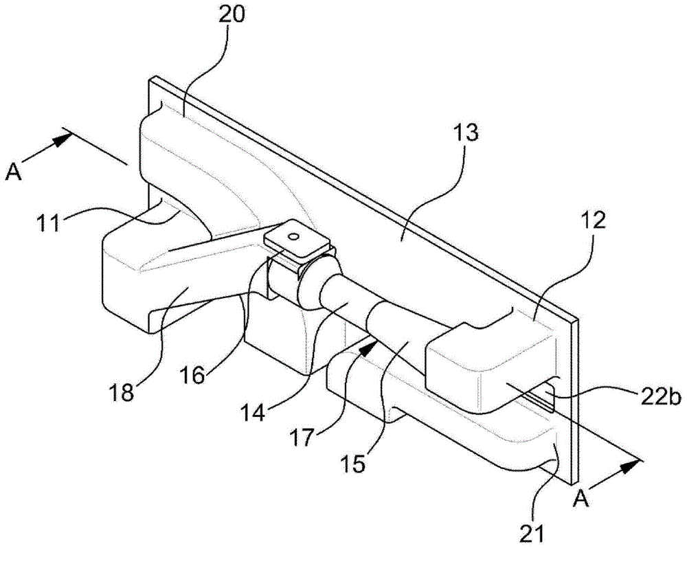
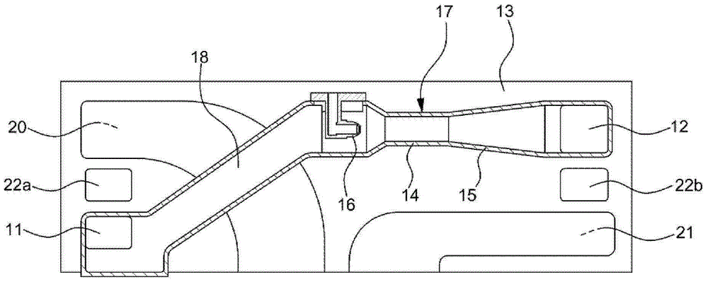
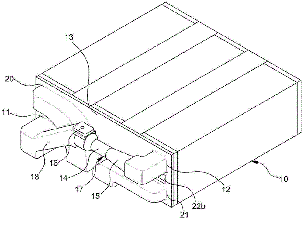
[0051] figure 1 and figure 2 is a perspective view and a cross-sectional view showing a fuel cell stack manifold having an injector function according to an embodiment of the present invention, image 3 is a perspective view showing installation / configuration of a fuel cell stack manifold having an injector function according to an exemplary embodiment of the present invention.

[0052] like Figures 1 to 3 As shown, the fuel cell stack manifold, connected to the fuel cell stack 10 to supply and distribute fuel, air and cooling water for the operation of the fuel cell stack, has an integral venturi tube in the anode line of the stack manifold. ) - injectors of diff...


PUM


Abstract

A fuel cell stack manifold having an ejector function of which the manufacturing cost and the weight can be reduced by optimizing hydrogen supply and recirculation channels and removing other members. hardware without a separate ejector structure for additionally attaching an ejector, of which the productivity can be improved by removing from an ejector assembly process. The fuel cell system minimizes joints through which hydrogen may leak, by implementing a new structure of a manifold added with an ejector function by integrally forming / manufacturing a stack manifold having a venturi and diffuser structure and adding a nozzle thereto.

Description

technical field [0001] The present invention relates to a fuel cell stack manifold for supplying and distributing hydrogen, air and cooling water for operating the fuel cell stack, and more particularly to a fuel cell incorporating injectors for recirculating stack exhaust gases stack manifold. Background technique [0002] Typically, a fuel cell is a generator that converts the chemical energy of fuel into electricity through electrochemical reactions in a fuel cell stack, rather than through combustion into heat. Such fuel cells can be used not only to power industries, homes and vehicles, but also to power small electrical / electronic products, especially portable devices. [0003] An automotive fuel cell system generally includes a fuel cell stack that generates electric power, a fuel supply device that supplies fuel (for example, hydrogen) to the fuel cell stack, an air supply device that supplies hydrogen in air as an oxidant for an electrochemical reaction to the fuel...

Claims


Application Information

Patent Timeline
Patent Type & Authority Applications(China)
IPC IPC(8): H01M8/02
CPCH01M8/2485H01M8/04097H01M2250/20H01M2008/1293Y02E60/50Y02P70/50Y02T90/40H01M8/0267H01M8/2484
Inventor 郑世权金悳焕鲁容奎权富吉
Owner HYUNDAI MOTOR CO LTD
Learn More