Automatic ash-cleaning spiral dust collection pole electric dedusting machine

A self-cleaning, spiral-type technology, applied in the direction of electrode structure, electrostatic separation, electrode cleaning, etc., can solve problems such as prone to failure, complicated vibration equipment, and delay in production time

Inactive Publication Date: 2015-08-05
广州高唐科技发展有限公司
View PDF9 Cites 4 Cited by
  • Summary
  • Abstract
  • Description
  • Claims
  • Application Information

AI Technical Summary

Problems solved by technology

However, most of the current electrostatic precipitators have a serious defect that once the dust collection plate is full of dust, the dust removal efficiency will be significantly reduced, or even lose its function. To solve this problem, people have invented a dust collection plate that can be removed. Take out the dust collection board to clean it when it is full of dust, because industrial dust collectors are generally very large in size, which brings trouble to disassembly, consumes a lot of manpower and material resources, and delays a lot of production time, seriously affecting Production efficiency, because manual cleaning is difficult to remove dust in time, so the dust removal performance is unstable
There are also some devices that use vibration to remove dust. The vibration equipment is composed of many dust collecting plates. There are multiple vibrators on the dust collecting plates and corona electrodes. The dust is shaken off, and the vibration equipment is complicated, which increases the investment of equipment. Due to frequent vibration, it is also prone to failure and inconvenient maintenance.

Method used


Image

  • Automatic ash-cleaning spiral dust collection pole electric dedusting machine
  • Automatic ash-cleaning spiral dust collection pole electric dedusting machine
  • Automatic ash-cleaning spiral dust collection pole electric dedusting machine

Examples


Embodiment

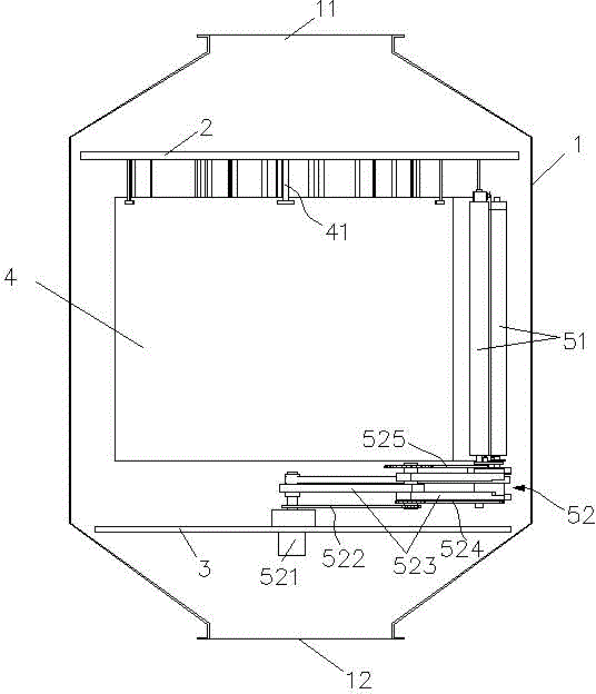
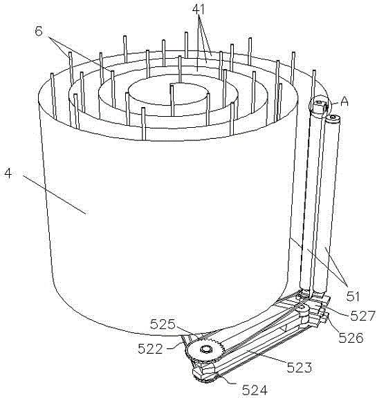
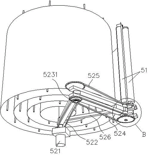
[0021] like Figure 1 to Figure 6 As shown, the present invention comprises shell 1, corona pole 6, dust collection pole 4, dust collection plate support 2 and corona pole support, high-voltage power supply device, cylindrical dust removal brush 51, dust removal brush driving device 52, and shell 1 up and down Respectively set as a conical constriction, the lower end is provided with an air inlet 12, and the upper end is provided with an air outlet 11, and the dust collection pole is arranged inside the shell, which is a vertically arranged equidistant spiral dust collection pole plate 4, etc. Distance refers to the equal spacing between two adjacent spiral plates, the linear shape formed by its cross section (horizontal section) is a plane spiral, the height of the dust collection plate is the same, and the corresponding position of the inner and outer sides of the spiral dust collection plate There is a pair of cylindrical dust removal brushes 51 that are in contact with the...


PUM


Abstract

The invention relates to an automatic ash-cleaning spiral dust collection pole electric dedusting machine, which comprises a shell, corona poles, a dust collection pole, a dust collection pole plate support and a corona pole support, a high voltage power supply device, cylindrical dedusting brushes, and a dedusting brush drive device. The dust collection pole is a vertically disposed isometric spiral dust collection pole plate, the cross section of which is a planar spiral line. The corresponding positions on the inner side and outer side of the spiral dust collection pole plate are provided with a pair of cylindrical dedusting brushes that contact the inner side and outer side of the dust collection pole plate and can roll to brush ash. The thread line type dust collection pole plate involved in the invention makes the dust collection pole plate structure very simple, convenient for making and processing, production and assembling, maintenance and disassembly, and more convenient for implementation of ash-cleaning automation. Compared with traditional dust collection plates, the electric dedusting machine saves more space, has larger dust collection area, can clean ash automatically, ensures high efficiency dust removal of products, has more stable and reliable working performance, avoids the hardship of human ash cleaning, and improves the work efficiency.

Description

technical field [0001] The invention relates to an electrostatic precipitator, in particular to a spiral dust collector electric precipitator for automatic dust removal. Background technique [0002] With the development of the economy, it has brought serious environmental pollution, and dust removal equipment has been produced to control pollution. Electrostatic dust removal equipment is one of the commonly used equipment. However, most of the current electrostatic precipitators have a serious defect that once the dust collection plate is full of dust, the dust removal efficiency will be significantly reduced, or even lose its function. To solve this problem, people have invented a dust collection plate that can be removed. Take out the dust collection board to clean it when it is full of dust, because industrial dust collectors are generally very large in size, which brings trouble to disassembly, consumes a lot of manpower and material resources, and delays a lot of produ...

Claims


Application Information

Patent Timeline
Patent Type & Authority Applications(China)
IPC IPC(8): B03C3/04B03C3/47B03C3/74
Inventor 王金志
Owner 广州高唐科技发展有限公司
Why Eureka
Try Eureka