
Energy-saving and cooling system for communication room with pre-dehumidification and cooling structure

A technology of cooling structure and communication room, applied in air conditioning system, space heating and ventilation details, household appliances, etc., can solve the problems of power consumption discount of power consumption fan, mechanical vibration of fan, and the system can not work normally, so as to achieve the guarantee Heat exchange efficiency, keeping air humidity, cost and energy consumption low

Active Publication Date: 2017-12-08
SICHUAN YUANCHANG NEW ENERGY TECH
View PDF7 Cites 0 Cited by
  • Summary
  • Abstract
  • Description
  • Claims
  • Application Information

AI Technical Summary

Problems solved by technology

However, this system has some defects in the actual use process: 1. When fresh outdoor air passes through the water-containing multi-layer corrugated fiber, the humidity of the air will be increased, especially in some areas where the air humidity itself is relatively high, which will inevitably cause The air humidity index exceeds the standard, which will affect the normal operation of the whole system; 2. Before the fresh outdoor air passes through the multi-layer corrugated fiber containing water, it needs to pass through the filter screen to process the dust impurities in the air. The filter screen is generally very fine, and the air passes through In addition, in order to enhance the cooling effect, the multi-layer corrugated fiber chooses a special complex and dense and fine labyrinth structure. It is very difficult for the air to pass through it. In this case, in order to allow the air to pass through, the fan power has to be increased, and the result is The reduced power consumption is greatly discounted by the power consumption of the fan, which makes the final actual figure of energy saving and emission reduction far from the expectation; 3. A direct consequence of the large power of the fan is that the noise will exceed the standard when the fan is running for a long time. The mechanical operation of the fan will definitely cause vibration, and the air pipe connected to it will also vibrate together. If resonance is formed, it will be difficult to eliminate the fault. Complaints and resentment are easy to be caused when the computer room and office area are integrated or adjacent to each other; 4 1. The inside of the base station in the computer room is in a positive wind pressure state, and the fresh air outside must rely on the fan, which does not meet the requirements of energy saving and emission reduction. A better working state should be a negative wind pressure state, which is beneficial to the fresh air outside without relying on power 5. When the water flows through the wet curtain, the water evaporates and loses, and scale will be formed in the holes of the wet curtain. Once the scale is generated, it will grow rapidly and accumulate, and finally the hole will be blocked. Once this kind of scale on the surface is formed, it cannot be removed at all, and must be replaced as a whole.

Method used


Image

  • Energy-saving and cooling system for communication room with pre-dehumidification and cooling structure
  • Energy-saving and cooling system for communication room with pre-dehumidification and cooling structure
  • Energy-saving and cooling system for communication room with pre-dehumidification and cooling structure

Examples


Embodiment 1

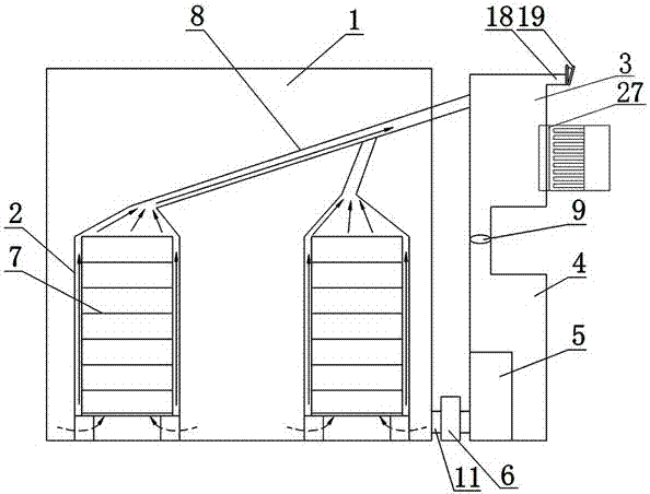
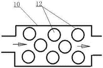
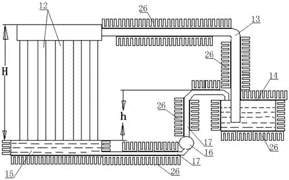
[0028] Such as Figure 1-Figure 3 As shown, the communication machine room energy-saving cooling system with a pre-dehumidification and cooling structure includes a machine room 1, and the bottom of the machine room 1 is provided with an air inlet pipe 11. The system also includes a grid room 2, a return air area 3, and The air inlet room 4, the cooling equipment 5 and the dust removal equipment 6; the air return area 3, the air inlet room 4, the cooling equipment 5 and the dust removal equipment 6 are all arranged outside the machine room 1, and the top of the grid room 2 is connected to the return air duct 8 through the air inlet pipe 8. The wind zone 3 is connected, and the return air zone 3 is connected to the air inlet room 4 through a pipeline, and a fan 9 is arranged on the pipeline; The heat chamber 10, the two ends of the heat exchange chamber 10 are respectively provided with an air inlet and an air outlet, the air inlet is connected to the air inlet room 4, the air ...

Embodiment 2

[0034] Such as figure 1 As shown, this embodiment adds the following structure on the basis of Embodiment 1: the air return area 3 is provided with an air inlet A18, and an air inlet control panel 19 is arranged on the air inlet A18.

[0035] In this embodiment, the external cold air can enter the return air area 3 through the air inlet A18 for supplementation, so as to prevent negative pressure from forming inside the return air area 3 and cause poor air flow and thus increase energy consumption. The air intake control panel 19 can be manually or manually Intelligent control system for switch control.

Embodiment 3

[0037] Such as figure 1 As shown, this embodiment has been further optimized on the basis of embodiment 1 or embodiment 2, specifically: a grid 7 for placing communication equipment is arranged inside the grid room 2, and at the bottom of the grid room 2 Vent holes are also provided.

[0038] In order to enhance the heat dissipation efficiency of communication equipment in this embodiment, a grid 7 for placing communication equipment is arranged inside the grid room 2. Communication equipment can be placed on the grid 7 in an orderly and hierarchical manner, which is convenient for installation and maintenance, and the communication equipment They are separated from each other to facilitate full contact with the cold air and enhance the heat dissipation effect. At the same time, the bottom of the grid room 2 is provided with ventilation holes, and the cold air enters through the ventilation holes and flows upward from the bottom of the grid room 2 and takes away the communicat...


PUM


Abstract

The invention discloses a communication machine room energy-saving cooling system. The communication machine room energy-saving cooling system comprises a machine room and a wind inlet pipe arranged at the bottom of the machine room, and further comprises a grillwork room, a wind return area, a wind inlet room, cooling equipment and dust removing equipment arranged in the machine room, wherein the top of the grillwork room is communicated with the wind return area through an air guide pipe; the wind return area is communicated with the wind inlet room through a pipe; a fan is arranged on the pipe; the cooling equipment is arranged in the wind inlet room; a heat exchange cavity is formed in the cooling equipment; a wind inlet and a wind outlet are respectively formed in the two ends of the heat exchange cavity; the wind inlet is communicated with the wind inlet room; the wind outlet is communicated with the wind inlet pipe through the dust removing equipment; multiple heat exchange pipes perpendicular to the wind direction in the heat exchange cavity are arranged in the heat exchange cavity; the top ends of the heat exchange pipes are communicated with a water inlet tank through pipelines A, and the bottom ends of the heat exchange pipes are communicated with a water outlet tank; the water outlet tank is communicated with the water inlet tank through a water pump and a water conveying pipe; and a semiconductor refrigerator is arranged in a wind return area. The system can pre-dehumidify air to keep the air humidity, and continuously blows wind to cool water to achieve good cooling effect.

Description

technical field [0001] The invention relates to an energy-saving and cooling system, and more specifically relates to an energy-saving and cooling system for a communication machine room with a pre-dehumidification and cooling structure. Background technique [0002] In the composition of the total energy consumption of communication equipment rooms and base stations, the energy consumption of air conditioners accounts for nearly half of the proportion. Reducing the use time of air conditioners and making full use of natural cooling sources (or other low-energy auxiliary cooling sources) to reduce energy consumption in computer rooms and base stations are key technical means for energy conservation and consumption reduction in communication computer rooms and base stations. At present, the cooling system that combines water evaporative air conditioner and fresh air is widely used. The working principle is that water is used as the evaporation medium. Water absorbs heat durin...

Claims


Application Information

Patent Timeline
Patent Type & Authority Patents(China)
IPC IPC(8): F24F5/00F24F13/30F24F13/32
CPCF24F5/0042F24F5/0046F24F13/30F24F13/32
Inventor 陈春到杨如民
Owner SICHUAN YUANCHANG NEW ENERGY TECH
Learn More