New type mixer power transmission mechanism

A technology of power transmission mechanism and mixer, which is applied to mixer accessories, mixers, mixers with rotating containers, etc., can solve the problems of obvious transmission mechanism noise, large load of mixing tank, and difficult process, and improve humanized design. , Improve the service life of the equipment and the effect of convenient operation

Inactive Publication Date: 2015-08-12
苏州亚玛达机械有限公司
View PDF5 Cites 3 Cited by
  • Summary
  • Abstract
  • Description
  • Claims
  • Application Information

AI Technical Summary

Problems solved by technology

[0003] However, the prior art mixer power transmission mechanism adopts the gear transmission mode. Due to the large load and vibration of the mixing tank, the transmission mechanism is noisy, easy to wear, and the process is difficult large, expensive to produce

Method used


Image

  • New type mixer power transmission mechanism
  • New type mixer power transmission mechanism
  • New type mixer power transmission mechanism

Examples


Embodiment 1

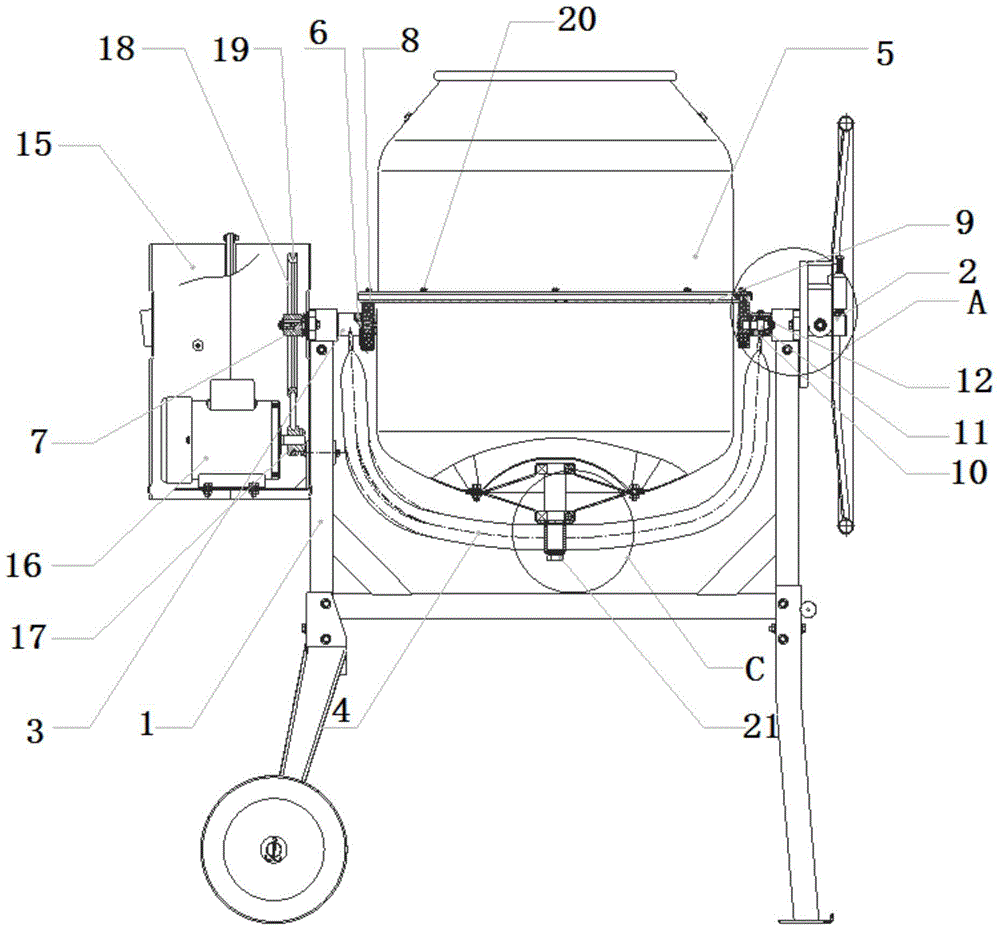
[0027] Embodiment 1: refer to figure 1 As shown, a new mixer power transmission mechanism includes a mounting bracket 1, a branch pipe 2 and a bearing seat 3 symmetrically fixed on the mounting bracket 1, a U-shaped bracket 4 fixedly connected to the branch pipe 2 and the bearing seat 3 at both ends, and the bottom The mixing pot body 5 that is connected with the U-shaped support 4 and can rotate freely, the driving device that is located on the mounting bracket 1, the supporting device that is located on the branch pipe 2, and the two bearings 6 that are fixed on the bearing seat 3, are set on two The main shaft 7 in the bearing 6, the friction wheel 8 fixedly connected with the output end of the main shaft 7, and the friction belt 9 fixed on the outer peripheral side of the stirring pot body 5; the output end of the driving device is connected with the input end of the main shaft 7, and the friction wheel One 8 and the supporting device are all connected with the friction...

Embodiment 2

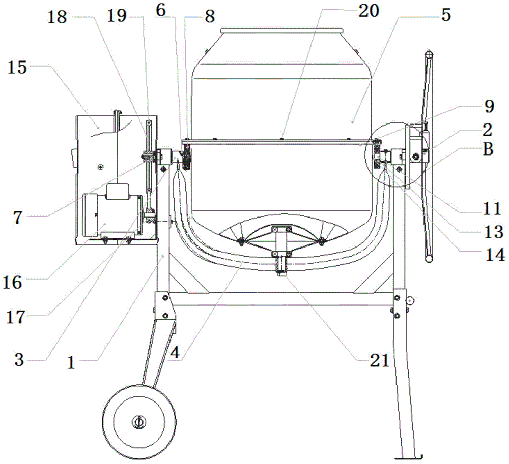
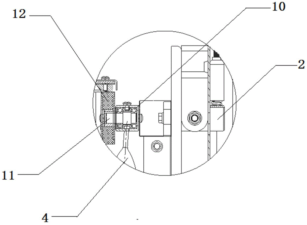
[0032] refer to figure 2 , 4 As shown, the main difference between the technical solutions of embodiment 2 and embodiment 1 is that the supporting device of the present invention includes a sub-shaft 11 fixed on the branch pipe 2, and a supporting wheel 13 which is arranged on the output end of the sub-shaft 11 and can rotate freely. , On the secondary shaft 11, a retaining ring 14 is arranged on the outside of the support wheel 13, and the support device plays a supporting and guiding role.


PUM


Abstract

The invention discloses a new type mixer power transmission mechanism, including a mounting bracket, a branch pipe, a bearing seat, a U-shaped bracket, a mixing pot body, a drive device, a support device, two bearings I, a main shaft, a friction wheel I, and a friction belt, wherein the branch pipe and the bearing seat are symmetrically and fixedly mounted on the mounting bracket, two end of the U-shaped bracket are respectively connected with the branch pipe and the bearing seat, the bottom of the mixing pot body is connected with the U-shaped bracket, the mixing pot body can freely rotate, the drive device is mounted on the bracket, the support device is mounted on the branch pipe, the two bearings I are fixed on the bearing seat, the two bearings I sleeve the main shaft, the friction wheel I is fixedly connected with the output end of the main shaft, the friction belt is fixed on the external circumference of the mixing pot body, the output shaft of the drive device is connected with the input end of the main shaft, and the friction wheel I and the support device are connected with the friction belt; the new type mixer power transmission mechanism has advantage of simple structure, and the difficulty of technology can be decreased by friction transmission between the friction wheel and the friction belt, the production cost is reduced, noise is reduced, and the humanized design of the machine operation can be improved.

Description

technical field [0001] The invention relates to a mixer, in particular to a novel mixer power transmission mechanism. Background technique [0002] Mixer is a machine that makes materials mix and flow evenly according to certain rules through mechanical action. It is mainly used in construction, small workshops, construction sites, etc. It can be used to mix cement, concrete, lime paste, paint and other building materials, and can also be used for fertilizers. , seeds, pesticides, feed and other agricultural and animal husbandry materials can also be used for mixing chemical products, such as plastic granules. [0003] However, the power transmission mechanism of the mixer in the prior art adopts a gear transmission mode. Due to the large load and vibration of the mixing tank, the transmission mechanism has obvious noise and is easy to wear, and the process is difficult and the production cost is high. Contents of the invention [0004] The purpose of the present inventio...

Claims


Application Information

Patent Timeline
Patent Type & Authority Applications(China)
IPC IPC(8): B01F9/02B01F15/00B01F29/60
Inventor 唐德友李洪
Owner 苏州亚玛达机械有限公司
Why Eureka
Try Eureka