
Apparatus for boring hole in steel tube

A steel pipe and drill bit technology, which is applied in the field of metal product processing machinery, can solve problems such as the drilling of metal pipes with different diameters, the concave area of ​​the upper hole of the metal pipe, and the impact on the quality of the metal pipe, so as to prevent subsidence and ensure the processing quality. , the effect of convenient operation

Active Publication Date: 2015-08-12
WUHU BEISI SCI & TECH PARK
View PDF7 Cites 23 Cited by
  • Summary
  • Abstract
  • Description
  • Claims
  • Application Information

AI Technical Summary

Problems solved by technology

This technical solution cannot well locate the position that needs to be drilled, and the machining accuracy is not high. Moreover, when drilling, it is easy to cause a concave area around the upper hole of the metal pipe, thereby affecting the quality of the metal pipe, and it is also not It can drill holes for metal pipes with different diameters, and this technical solution needs further improvement

Method used


Image

  • Apparatus for boring hole in steel tube
  • Apparatus for boring hole in steel tube
  • Apparatus for boring hole in steel tube

Examples


Embodiment 1

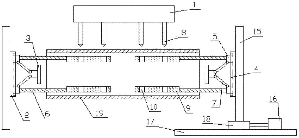
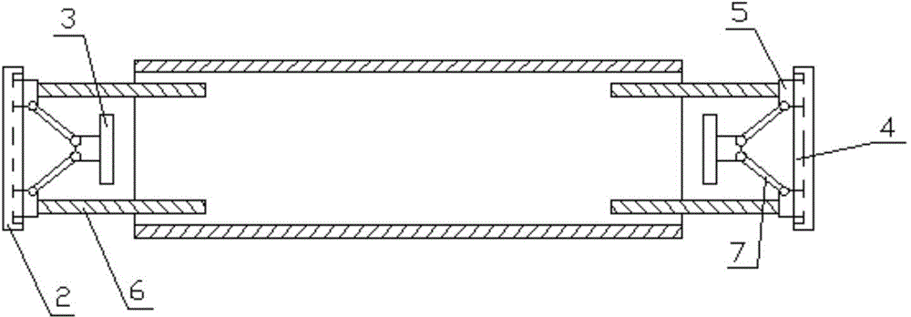
[0038] combine figure 1 : A device for drilling steel pipes, comprising a drilling unit 1 and at least one supporting unit;

[0039] The support unit includes a support plate 2 and a hydraulic cylinder 3. The support plate 2 is provided with a first chute 4, and the first chute 4 is provided with two first sliders 5, and each first slider 5 has a There is a support plate 6, two support plates 6 are arranged parallel to each other, and the two first sliders 5 are connected to the hydraulic cylinder 3 through a connecting rod 7 of equal length;

[0040] Drilling unit 1 comprises several drill bits 8, and the extension direction of this drill bit 8 is perpendicular to the direction that support plate 6 extends, and this drill bit 8 is distributed along the extension direction of support plate 6, and the horizontal distance between this drill bit 8 and two support plates 6 Equal, otherwise, drill bit 8 can not carry out drilling along the radial direction of steel pipe 19.

[00...

Embodiment 2

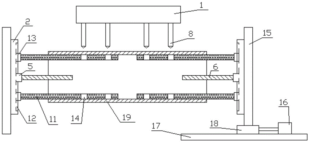
[0056] combine figure 2 , 3 , 4: A device for drilling steel pipes, including a drilling unit 1 and at least one supporting unit;

[0057] The support unit includes a support plate 2 and a hydraulic cylinder 3. The support plate 2 is provided with a first chute 4, and the first chute 4 is provided with two first sliders 5, and each first slider 5 has a There is a support plate 6, two support plates 6 are arranged parallel to each other, and the two first sliders 5 are connected to the hydraulic cylinder 3 through a connecting rod 7 of equal length;

[0058] Drilling unit 1 comprises several drill bits 8, and the extension direction of this drill bit 8 is perpendicular to the direction that support plate 6 extends, and this drill bit 8 is distributed along the extension direction of support plate 6, and the horizontal distance between this drill bit 8 and two support plates 6 Equal, otherwise, drill bit 8 can not carry out drilling along the radial direction of steel pipe 19...


PUM


Abstract

Disclosed in the invention is an apparatus for boring a hole in a steel tube. The apparatus comprises a hole boring unit and at least one support unit. The support unit consists of a support plate and a hydraulic cylinder; a first chute is formed in the support plate and two first sliding blocks are arranged in the first chute; each first sliding block is provided with one support plate and the two support plates are parallel to each other; the two first sliding blocks are in transmission connection with the hydraulic cylinder by connecting rods with equal lengths. The hole boring unit contains a plurality of drilling heads, wherein the extending directions of the drilling heads are perpendicular to the extending directions of the support plates; and the drilling heads are distributed along the extending directions of the support plates; and horizontal distances between the drilling heads and the two support plates are equal. According to the invention, on the basis of the support unit design, the processing precision can be guaranteed even steel tubes with different diameters and different lengths are processed; and hole boring work can be carried out at different positions of the steel tubes can be carried out. With designs of a first extending plate and a second extending plate, sinking of walls of the steel tubes can be effectively prevented, thereby guaranteeing the processing quality.

Description

technical field [0001] The invention relates to the technical field of metal product processing machinery, in particular to a device for drilling steel pipes. Background technique [0002] Drilling the steel pipe in the radial direction requires passing the drill pipe through the diameter line of the center of the steel pipe; in the axial direction, it is required to be perpendicular to the axis. Moreover, multiple holes need to be drilled on a steel pipe, and the centerlines of all the holes are required to be parallel. Since the axis is a virtual line, it is very difficult to process multiple drilling holes that are circular and perpendicular to the axis. The traditional method is to draw a line and mark the position where the hole will be punched on the steel pipe. Then use the drill to drill the marked points. In fact, this processing method is very rough and the precision is not high. It mainly depends on the experience of the workers. [0003] In Chinese Patent Appl...

Claims


Application Information

Patent Timeline
IPC IPC(8): B23B41/00B23B47/00B23Q3/08
CPCB23B31/4073B23B39/161B23B2215/72B23B2270/20
Inventor 戴巧子
Owner WUHU BEISI SCI & TECH PARK
Features
  • Generate Ideas
  • Intellectual Property
  • Life Sciences
  • Materials
  • Tech Scout
  • Unparalleled Data Quality
  • Higher Quality Content
  • 60% Fewer Hallucinations
Learn More