Eureka AIR delivers breakthrough ideas for toughest innovation challenges, trusted by R&D personnel around the world.

Novel auger bit

A twist drill bit, a new type of technology, applied in the direction of twist drills, etc., can solve the problems of low efficiency, low precision, and many processes, and achieve the effect of large cutting area, fast cutting speed, and not easy to break

Inactive Publication Date: 2015-08-12
启东市吕四科技创业中心有限公司
View PDF0 Cites 1 Cited by
  • Summary
  • Abstract
  • Description
  • Claims
  • Application Information

AI Technical Summary

Problems solved by technology

[0004] The technical problem to be solved by the present invention is to solve the problem of many processes, low efficiency, multiple processing, poor concentricity and low precision, which cannot meet the needs of high-precision products

Method used


Image

  • Novel auger bit

Examples


Embodiment Construction

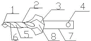
[0019] Reference numerals: 1, drill tip, 2, main cutter, 3, auxiliary cutter, 4, positioning groove, 5, row cutting groove, 6, front end of drill body, 7, drill shank, 8, drill rear end of body

[0020] In order to make the purpose, technical solution and advantages of the present invention clearer, the following will further describe the implementation of the present invention in detail in conjunction with the accompanying drawings.

[0021] The structure of twist drill bit of the present invention is as figure 1 As shown, a novel twist drill bit is formed by connecting two parts of a drill shank 7 and a drill body. The drill body front end 6 of the ∞-shaped body with straight end faces at both ends and the drill body rear end 8 of the ∞-shaped body with straight end faces at both ends of the large diameter are integrally formed on the same axis. Along the ∞-shaped part, there is an S-shaped main cutter 2 arranged horizontally. The S-shaped main cutter 2 and the drill body ...


PUM

PropertyMeasurementUnit
Lengthaaaaaaaaaa

Abstract

The invention discloses a novel auger bit. The novel auger bit is formed by connecting a drill handle and a drill body. The novel auger bit is characterized in that the structure of the drill body is composed of a drill point and a main drill body in an integrated forming mode; the main drill body is formed in the manner that an 8-shaped drill body front end part with the small diameter and an 8-shaped drill body rear end part with the large diameter are integrally formed in the same axis, wherein the two ends of the 8-shaped drill body front end part with the small diameter are straight end faces, and the two ends of the 8-shaped drill body rear end part with the large diameter are straight end faces; a horizontal S-shaped main cutter is arranged on the drill body front end part along the 8-shaped part, a horizontal S-shaped auxiliary cutter is arranged on the drill body rear end part along the 8-shaped part, the drill handle is of a fine and long cylinder structure, and a positioning groove is formed in the position, close to the end, of one end of the drill handle. According to the novel auger bit, the drill point, the main cutter, the auxiliary cutter and a chip removal structure are effectively combined, three-level drilling and one-time forming are achieved, chip removal is smooth, and the smoothness of the drilling cut face is achieved.

Description

technical field [0001] The invention belongs to the field of drill bits, in particular to a novel twist drill bit. Background technique [0002] The drill bit is a tool that rotates and has cutting ability at the head end. It is generally made of carbon steel SK, or high-speed steel SKH2, SKH3 and other materials after milling or rolling and then quenched, tempered and heat-treated. It is used for metal Or drilling on other materials, it has a wide range of applications, and can be used on drilling machines, lathes, milling machines, hand drills and other machine tools. [0003] Twist drill is a tool for drilling circular holes in workpieces by rotating and cutting relative to a fixed axis. At present, when the workpiece is drilled, due to the large diameter of the twist drill bit, it is often difficult to advance the drill bit, and in severe cases, the drill bit will be irreparably damaged. In order to ensure the high precision of the processed holes, it is necessary ...

Claims


Application Information

Patent Timeline
IPC IPC(8): B23B51/02
CPCB23B51/02
Inventor 潘永新
Owner 启东市吕四科技创业中心有限公司
Why Eureka
Eureka Blog
Learn More