
Structure of IGBT chip

A chip, PN junction technology, applied in electrical components, circuits, semiconductor devices, etc., can solve problems such as rising costs and increasing difficulty in subsequent packaging, and achieve the effects of improving reliability, good switching speed, and reducing material consumption

Active Publication Date: 2015-08-12
乐山希尔电子股份有限公司 +1
View PDF6 Cites 7 Cited by
  • Summary
  • Abstract
  • Description
  • Claims
  • Application Information

AI Technical Summary

Problems solved by technology

And because the IGBT itself is only a unidirectional conduction device, a diode needs to be connected in parallel to withstand the reverse voltage in the application, which increases the difficulty of the subsequent packaging and increases the cost

Method used


Image

  • Structure of IGBT chip
  • Structure of IGBT chip
  • Structure of IGBT chip

Examples


Embodiment 1

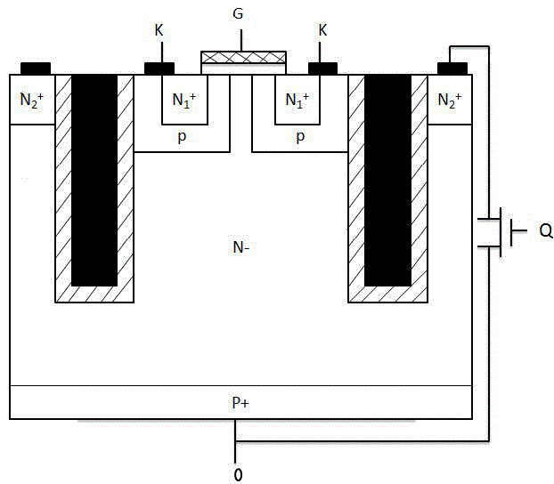
[0028] A structure of an IGBT chip, including an IGBT unit composed of a MOS field effect transistor and a triode, and also includes a control switch Q, an electrode N 2 + and an isolation cover, the IGBT unit is set inside the isolation cover, and the isolation cover is set on the electrode N 2 + Inside, the control switch Q is connected to the electrode N respectively. 2 + It is connected with the triode, when the IGBT unit conducts forwardly, the control switch Q is in the off state, and when the IGBT unit conducts in the reverse direction, the control switch Q is in the open state.

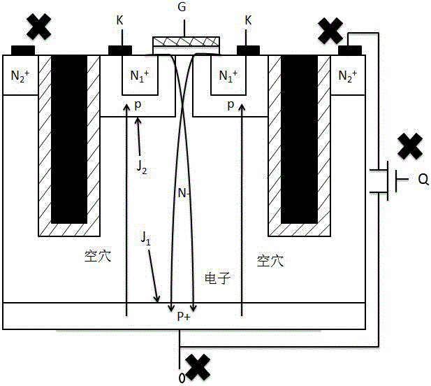
[0029] In this embodiment, when the IGBT unit is in the forward conducting state, the control switch Q is in the closed state, and the PN junction J 2 In reverse bias, J 1 in a forward biased state.

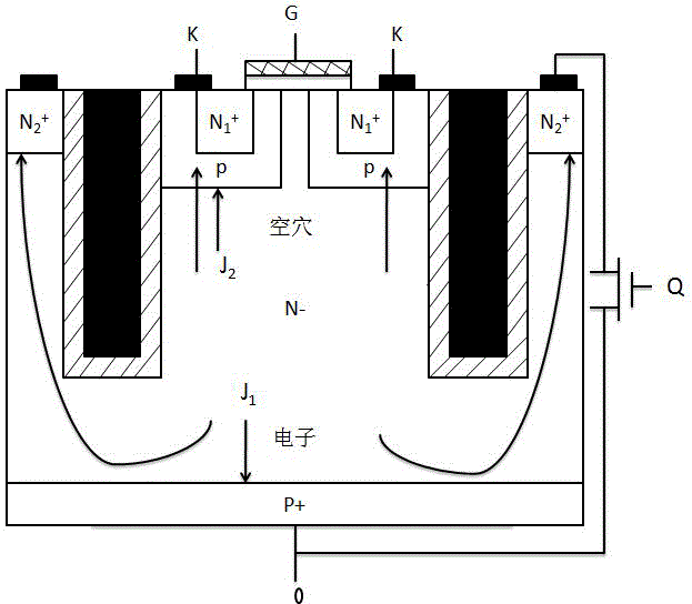
[0030] In this embodiment, when the IGBT unit is in reverse conduction, the control switch Q is in the open state, and the PN junction J 1 In the reverse bias state, the PN junction J 2 I...

Embodiment 2

[0039] The present invention is a gate-type high-speed IGBT structure, which introduces an isolation cover, N 2 + and device Q. When the IGBT is in the forward conduction, the PN junction J 2 In the reverse biased state, the PN junction J 1 In the forward-biased state, because of the isolation cover, it plays an isolation role, because there is enough thick insulating material in the isolation cover, for N 2 + There is no effect, so that the IGBT is the same as the traditional IGBT in the forward conduction state, and the direction of the current is as figure 2 So style. When the IGBT is in the reverse direction, J 1 In reverse bias state, J 2 In positive bias, electrons will flow out because of P + The influence of the potential barrier is hindered, and electrons have to overcome the potential barrier block Hard work will generate heat, the more the number of electrons, the greater the heat, which will affect the reliability of the device. Therefore, at present, th...


PUM


Abstract

The invention discloses a structure of an IGBT chip, which comprises an IGBT unit that is composed of an MOS field effect transistor and a triode. The IGBT chip further comprises a control switch Q, electrodes N2<+> and an isolating cover. The IGBT unit is arranged in the isolating cover. The isolating cover is arranged in the electrode N2<+>. The control switch Q is connected with the electrode N2<+> and the triode. When the IGBT unit is conducted in the forward direction, the control switch Q is in an off state; and when the IGBT unit is conducted in the backward direction, the control switch Q is in an on state. The structure of the IGBT chip has functions of basically settling a problem of snapback without influence to the performance parameter, effectively integrating a diode in the IGBT, truly realizing low conduction voltage drop and good switching speed of the IGBT, and greatly improving device reliability.

Description

technical field [0001] The invention relates to a structure of an IGBT chip and belongs to the technical field of semiconductor devices. Background technique [0002] Because IGBT has excellent characteristics such as high frequency, high current, and high reverse voltage, it is widely used in automobiles, high-speed rail, home appliances, power electronics, aerospace, military and other fields. In recent years, various new processes and technologies of IGBT have emerged and produced continuously, making the performance of IGBT more perfect and excellent. For example, a trench gate IGBT chip disclosed in Chinese Patent Publication No. 12-03. Another example is a high-speed IGBT disclosed in Chinese Patent Publication No. "101494239", whose publication date is 2009-07-29. [0003] However, there are still some problems in the existing IGBT devices that need to be solved, or cannot be solved satisfactorily, such as the snapback problem, which will affect the heating of the d...

Claims


Application Information

Patent Timeline
IPC IPC(8): H01L29/739
CPCH01L29/7398
Inventor 邓华鲜
Owner 乐山希尔电子股份有限公司
Learn More