Coke oven gas waste heat recovery system

A waste heat recovery system and coke oven gas technology, which are applied to the heating of coke ovens, coke ovens, and dry distillation gas discharge devices, etc., can solve the problems of wasting sensible heat of coke oven gas, damage to waste heat recovery devices, and increasing ammonia water processing capacity. , to achieve the effect of improving waste heat recovery efficiency, easy vaporization, and improving stability

Active Publication Date: 2015-08-19
WISDRI ENG & RES INC LTD
View PDF9 Cites 3 Cited by
  • Summary
  • Abstract
  • Description
  • Claims
  • Application Information

AI Technical Summary

Problems solved by technology

The coke oven gas produced by the coke oven flows into the gas collecting pipe through the ascending pipe and the bridge pipe at the top of the coking chamber. Usually, ammonia water is sprayed into the bridge pipe to cool the coke oven gas at about 650~700°C to 84°C, which not only wastes a lot of coke oven gas Sensible heat of gas also increases ammonia treatment capacity
Scholars at home and abroad have studied the recovery of sensible heat of coke oven gas for many years but have not yet achieved success. One of the reasons is that the temperature of the gas is about 700 °C during the coking process, and the temperature of the riser and bridge tubes during coking and coal charging Sudden drop in temperature will cause periodic thermal shocks to the waste heat recovery device, resulting in damage and even production accidents

Method used


Image

  • Coke oven gas waste heat recovery system
  • Coke oven gas waste heat recovery system
  • Coke oven gas waste heat recovery system

Examples


Embodiment Construction

[0024] The following will clearly and completely describe the technical solutions in the embodiments of the present invention with reference to the accompanying drawings in the embodiments of the present invention. Obviously, the described embodiments are only some, not all, embodiments of the present invention. Based on the embodiments of the present invention, all other embodiments obtained by persons of ordinary skill in the art without making creative efforts belong to the protection scope of the present invention.

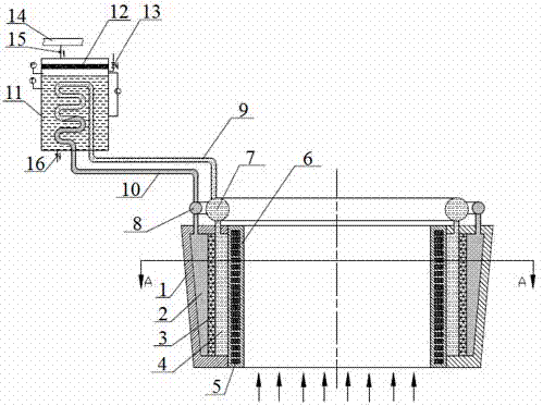
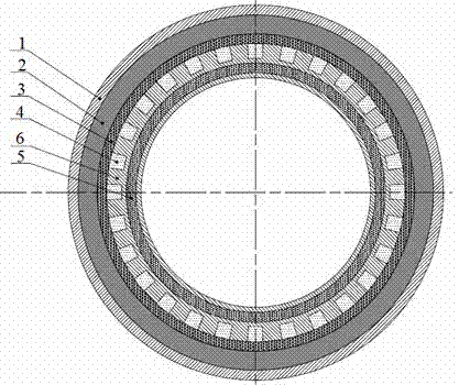
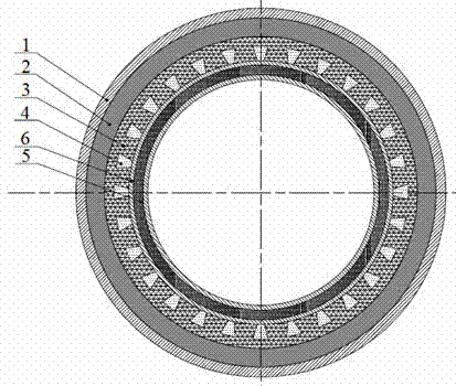
[0025] Such as figure 1 , The embodiment of the present invention provides a coke oven gas waste heat recovery system, the coke oven gas is produced by a coke oven, and the coke oven includes a plurality of carbonization chambers, and each of the carbonization chambers is connected with a coke oven gas guiding pipeline. The waste heat recovery system includes a split heat pipe, and the split heat pipe includes an evaporator device and a condenser; the evaporat...


PUM

PropertyMeasurementUnit
melting pointaaaaaaaaaa

Abstract

The invention relates to a coke oven gas waste heat recovery system. The coke oven gas waste heat recovery system comprises a split-type heat pipe, the split-type heat pipe comprises an evaporator device and a condenser, the evaporator device comprises a heat absorbing surface region formed by a coke oven gas guiding pipeline, the condenser comprises a steam pocket and a condenser pipeline arranged in the steam pocket, the inlet end of the condenser pipeline is communicated with a working medium outlet of the evaporator device via a gas working medium pipeline, the outlet end of the condenser pipeline is communicated with a working medium inlet of the evaporator device via a liquid working medium pipeline, a fill cavity is arranged in the heat absorbing region, and a phase-change material layer is arranged in the heat absorbing region. The coke oven gas waste heat recovery system has the advantages that by means of reconstructing the coke oven gas guiding pipeline (an ascension pipe and a bridge pipe) into the evaporator with the split-type heat pipe, coke oven gas waste heat can be recovered by the split type heat pipe; by means of arranging the phase-change material layer in the heat absorbing region, generation of periodic heat shock to a waste heat recovery device can be avoided, and waste heat recovery and production stability are improved effectively.

Description

technical field [0001] The invention relates to coke oven gas sensible heat recovery technology, in particular to a coke oven gas waste heat recovery system. Background technique [0002] The coke oven is a large-scale kiln that heats the coking coal in isolation from the air and produces coke by dry distillation. During the coking process, a large amount of coke oven gas and coke oven flue gas that is used for heating and exhausted are generated at the same time. The heat output from the coke oven is Among them, the sensible heat of coke oven gas accounts for about 36%, the sensible heat of baked red coke accounts for about 37%, the heat taken away by coke oven flue gas accounts for about 17%, and the heat dissipation on the surface of the furnace body accounts for about 10%. The coke oven gas produced by the coke oven flows into the gas collecting pipe through the ascending pipe and the bridge pipe at the top of the coking chamber. Usually, ammonia water is sprayed into th...

Claims


Application Information

Patent Timeline
Patent Type & Authority Applications(China)
IPC IPC(8): C10B27/00
CPCY02P20/129
Inventor 施万玲盖东兴
Owner WISDRI ENG & RES INC LTD
Why Eureka
Try Eureka