Eureka AIR delivers breakthrough ideas for toughest innovation challenges, trusted by R&D personnel around the world.

Absorption cavity type laser breakdown detection device

A detection device and laser breakdown technology, which is applied in the field of spectral measurement, can solve the problem that the detection sensitivity is difficult to meet higher detection requirements, and achieve the effect of small spectral line broadening effect, preventing interference and improving sensitivity

Inactive Publication Date: 2015-08-19
NANJING INST OF ADVANCED LASER TECH
View PDF6 Cites 4 Cited by
  • Summary
  • Abstract
  • Description
  • Claims
  • Application Information

AI Technical Summary

Problems solved by technology

At present, the detection limit of laser-induced breakdown spectroscopy is on the order of ppm, and the detection sensitivity is difficult to meet the higher detection requirements.

Method used


Image

  • Absorption cavity type laser breakdown detection device
  • Absorption cavity type laser breakdown detection device

Examples


Embodiment 1

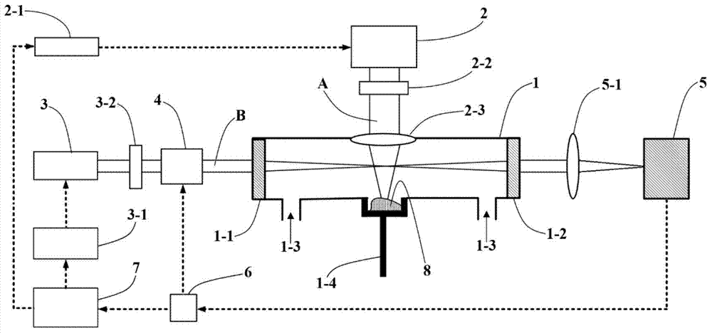
[0029] figure 1 is the basic structure diagram of this embodiment. The excitation light source 2 uses a pulsed Nd:YAG laser that emits a pulsed laser at 1064nm, while the detection light source 3 uses a continuously tunable Ti:Sapphire ring continuous laser with a tunable range of 700-900nm and an output power between 1000-1700W . The efficiency of the first-order diffraction of the AOM 4 is about 85%, and the zero-order diffraction spot is blocked by a small hole diaphragm ( figure 1 Not shown in), the operating frequency is 80MHz. The reflectivity of the two high reflection mirrors of the absorption cavity 1 is 99.995%, the radius of curvature is 1m, the cavity length of the absorption cavity 1 is 1.25m, and the free spectral range of the corresponding ring-down cavity is 120MHz. Absorbing cavity 1 has a ring-down time of 80 μs when there is no sample and is in a vacuum state, the fineness of the cavity is 50000, and the full width at half maximum of the mode in the cavit...

Embodiment 2

[0038] On the basis of embodiment 1, an annular piezoelectric ceramic ( figure 1not shown in ), the output mirror can change the cavity length of the ring-down cavity driven by the piezoelectric ceramic, that is, the cavity length is modulated by the piezoelectric ceramic; the cavity length change under the piezoelectric ceramic modulation is slightly greater than λ / 2 of the detection light, The cavity mode is made to oscillate around the laser frequency.

[0039] When used as a detection light source in the mode of step-scanning, each step is about 0.2s, and the piezoelectric ceramic is set to vibrate at a frequency of 300Hz, so that the detection light is more easily coupled into the absorption cavity, and the detection accuracy is increased.


PUM


Abstract

The invention discloses an absorption cavity type laser breakdown detection device which comprises an absorption cavity, an excitation light source, a detection light source, an acousto-optic modulation device, a light detector and an electronic control system for controlling the working process. According to the absorption cavity type laser breakdown detection device, a laser-induced breakdown technology and a light ring-down technology are combined; a sample to be detected is placed in a ring-down cavity; excitation light is focused and enters to the sample to be detected; under heat absorption, a nano particle cloud cluster is formed by the sample to be detected and is dispersed into the cavity; the detection light is reflected back and forth between high-reflectivity mirrors at the two ends of the ring-down cavity and is continuously absorbed by corresponding substances; the detector outside the cavity is used for detecting an emergent signal, so that the content of the substances can be calculated. By combination of the laser induced breakdown and light ring-down technologies, by use of the high-reflectivity mirrors, the detection extreme can be ppb level; before excitation light irradiation, the absorption cavity is vacuumized, so that interference of other components in air can be prevented, and widening of a spectral line can be reduced; therefore, the detected spectral line is easy to distinguish, and the flexibility is improved.

Description

technical field [0001] The invention relates to the technical field of spectrum measurement, in particular to an absorption cavity type laser breakdown detection device, which improves the detection limit in combination with optical ring-down technology. Background technique [0002] The currently commonly used laser-induced breakdown spectroscopy is a laser ablation spectral analysis method. The laser is focused on the sample (which can be solid, liquid or gas) through a lens. When the energy density of the laser is greater than the breakdown threshold of the sample When the plasma is generated locally, the local energy density and temperature of this plasma are very high, and the signal of the emission line generated on the plasma surface of the sample to be tested can be collected by a spectrometer, and can be quantified according to the intensity of the emission line Analyze the concentration of substances inside. At present, the detection limit of laser-induced breakdo...

Claims


Application Information

Patent Timeline
IPC IPC(8): G01N21/63
Inventor 王欢李建春陈昱
Owner NANJING INST OF ADVANCED LASER TECH
Why Eureka
Eureka Blog
Learn More