
System and method for overcurrent protection and voltage monitoring device burn-in test

A technology of voltage monitoring and overcurrent protection, applied in the direction of measuring devices, measuring electricity, measuring electrical variables, etc., can solve the problem of lack of troubleshooting and reliability testing methods for potential failures of voltage monitoring devices, failure to analyze the life of old cards, and test content Single and other problems, to achieve the effect of reducing operational risk, realizing fault discrimination, and efficient combination analysis process

Active Publication Date: 2015-08-19
CHINA GENERAL NUCLEAR POWER OPERATION +2
View PDF7 Cites 13 Cited by
  • Summary
  • Abstract
  • Description
  • Claims
  • Application Information

AI Technical Summary

Problems solved by technology

Under normal circumstances, the replacement of this series of overcurrent protection and voltage monitoring devices depends on manual calibration or detection, and the working cycle of the card is only determined by visual identification or regular inspection of the components of the overcurrent protection and voltage monitoring device. The test content is single and the operation is complicated. It is impossible to automatically analyze the life of the old card, and it lacks the troubleshooting and reliability detection methods for the hidden dangers of overcurrent protection and voltage monitoring devices.

Method used


Image

  • System and method for overcurrent protection and voltage monitoring device burn-in test
  • System and method for overcurrent protection and voltage monitoring device burn-in test
  • System and method for overcurrent protection and voltage monitoring device burn-in test

Examples


Embodiment Construction

[0049] In order to have a clearer understanding of the technical features, purposes and effects of the present invention, the specific implementation manners of the present invention will now be described in detail with reference to the accompanying drawings.

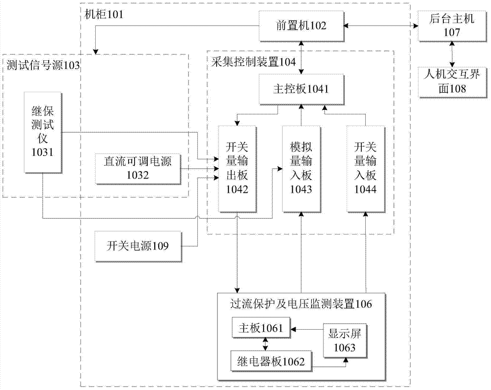
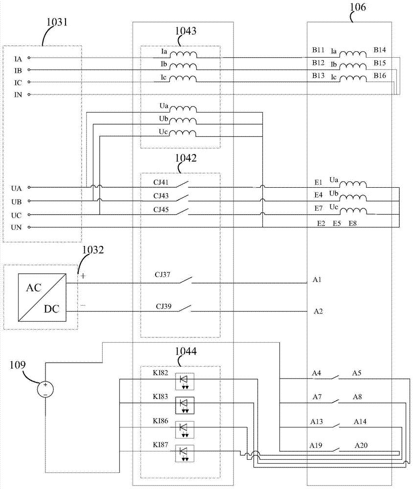
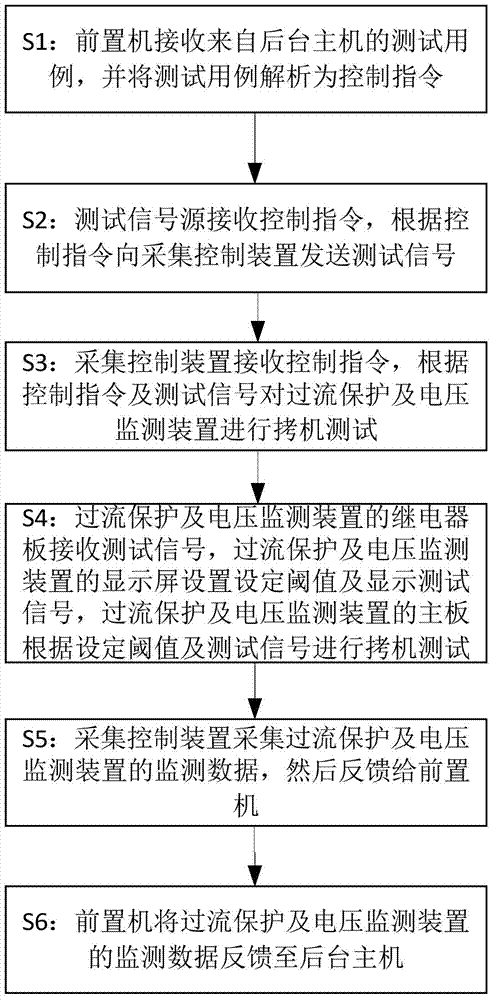
[0050] figure 1Shown are the over-current protection and voltage monitoring device copy-in test system in some embodiments of the present invention, which are used for copy-out testing of the over-current protection and voltage monitoring device 106 . The overcurrent protection and voltage monitoring device copying test system includes a man-machine interface 108, a background host 107, a test signal source 103, a front-end processor 102, an acquisition control device 104, an overcurrent protection and voltage monitoring device 106, and a switching power supply 109. Wherein, the overcurrent protection and voltage monitoring device 106 is electrically connected with the acquisition control device 104, and the switching p...


PUM


Abstract

The invention discloses a system and a method for overcurrent protection and voltage monitoring device burn-in test. The system comprises a cabinet, a front-end processor, a test signal source, an acquisition control device, and a switching power supply. The method comprises: the front-end processor parsing a test case to a control command; the test signal source sending test signals to the acquisition control device; the acquisition control device receiving the control command, and acquiring monitored data of the overcurrent protection and voltage monitoring device, and feeding back to the front-end processor. The overcurrent protection and voltage monitoring device comprises a relay panel, a mainboard, and a display screen. The relay receives test signals. The display screen sets a given threshold value. The mainboard receives a burn-in test. The system and the method for overcurrent protection and voltage monitoring device burn-in test use automated, intelligent, and integrated online monitoring measures, and can accurately and efficiently test functions of the overcurrent protection and voltage monitoring device, and can find out defects of the overcurrent protection and voltage monitoring device, so as to effectively reduce fault risks of nuclear power station circuits.

Description

technical field [0001] The invention relates to the on-line monitoring technology of power equipment in nuclear power plants, in particular to a copying test system and method for overcurrent protection and voltage monitoring devices in nuclear power plants. Background technique [0002] The over-current protection and voltage monitoring device is one of the important components of nuclear power plant circuit protection. It is mainly used for over-current protection of the circuit in the power grid system of the nuclear power plant, and can display the voltage value of the bus in the system. Once the safe setting current value and action time are set, when the current in the circuit exceeds the setting range, the overcurrent protection and voltage monitoring device will control the internal relay to operate, thereby disconnecting the circuit and preventing accidents. However, during long-term operation, the circuits on the overcurrent protection and voltage monitoring device...

Claims


Application Information

Patent Timeline
IPC IPC(8): G01R31/00
Inventor 胡振华滕杰白世杰段贤稳刘斌屈天龙
Owner CHINA GENERAL NUCLEAR POWER OPERATION
Learn More