Time relaxation-intertwined zeroing dynamic element matching encoder

A technology of dynamic component matching and time relaxation, applied in digital-to-analog converters, physical parameter compensation/prevention, etc., can solve serious power consumption, area and design complexity, mathematical derivation and specific implementation complexity, and realization complexity growth, etc. problem, to achieve the effect of ensuring the degree of randomization and dynamic characteristics, simple structure, and reducing complexity

Active Publication Date: 2015-08-19
TSINGHUA UNIV
View PDF4 Cites 5 Cited by
  • Summary
  • Abstract
  • Description
  • Claims
  • Application Information

AI Technical Summary

Problems solved by technology

When the precision of the DAC is high, that is, when n is large, the implementation complexity of the ideal DEM encoder increases exponentially with the precision, which brings serious problems of power consumption, area and design complexity
[0007] To this end, Galton et al. proposed a segmented DEM method (Dynamic Element Matching to Prevent Nonlinear Distortion From Pulse-Shape Mismatches in High-Resolution DACs published on JSSC in 2008), which can reduce the complexity of the DEM encoder to a certain extent, but Its mathematical derivation and specific implementation are still relatively complicated
Wei-Te Lin et al. proposed a dynamic component matching method based on "circular displacement of random digits" (A Compact Dynamic Performance Improved Current-Steering DAC With Random RotationBasedBinaryWeighted Selection published on JSSC in 2012), which is achieved by shifting random digits through control signals Encoder randomization, this method is relatively simple to implement, but the randomness of encoding is greatly limited, and when the number of encoder bits is high, it still has a more complex structure

Method used


Image

  • Time relaxation-intertwined zeroing dynamic element matching encoder
  • Time relaxation-intertwined zeroing dynamic element matching encoder
  • Time relaxation-intertwined zeroing dynamic element matching encoder

Examples


Embodiment Construction

[0023] Embodiments of the present invention are described in detail below, examples of which are shown in the drawings, wherein the same or similar reference numerals designate the same or similar elements or elements having the same or similar functions throughout. The embodiments described below by referring to the figures are exemplary only for explaining the present invention and should not be construed as limiting the present invention.

[0024] A time-relaxed interleaved return-to-zero dynamic element matching encoder according to an embodiment of the present invention will be described below with reference to the accompanying drawings.

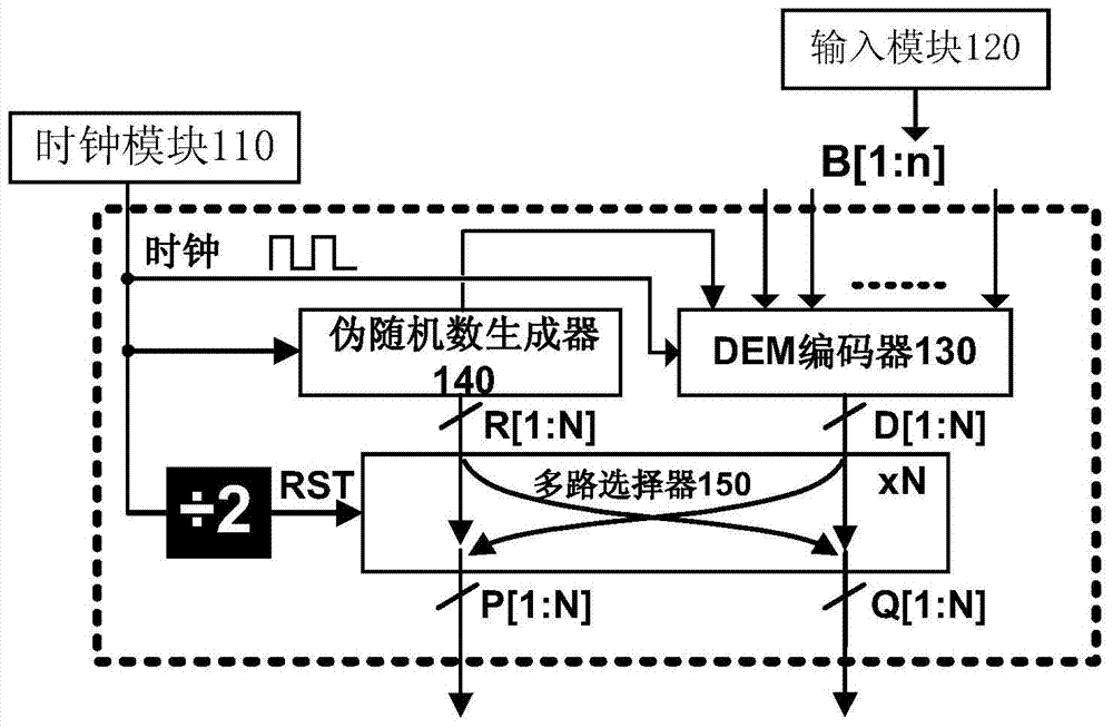
[0025] figure 2 is a structural schematic diagram of a time-relaxed interleaved return-to-zero dynamic element matching encoder according to an embodiment of the present invention. Such as figure 2 As shown, the time-relaxed interleaved return-to-zero dynamic element matching (Time-Relaxed Interleaving Return-to-Zero Dynamic Element...


PUM


Abstract

The invention provides a time relaxation-intertwined zeroing dynamic element matching encoder, which is characterized by comprising a clock module, an input module, a dynamic element matching encoder, a pseudo-random number generator, and an N-bit either-or multichannel selector, wherein the clock module is used for providing a clock signal; the input module is used for inputting an n-bit binary number B to the dynamic element matching encoder, and B=BnBn-1...B2B1, and B is no less than 0 but no more than 2n-1; the dynamic element matching encoder is used for generating an N-bit binary number D according to the clock signal and the n-bit binary number B, D=DNDN-1...D2D1, N=2n, D1+D2+...+DN=B, and DN=O; the pseudo-random number generator is used for generating an N-bit binary number R according to the clock signal, R=RNRN-1...R2R1, and R1+R2+...+RN=N/2; and the N-bit either-or multichannel selector is respectively connected with the clock module, the dynamic element matching encoder and the pseudo-random number generator for receiving R and D and generating a binary number P and a binary number Q according to R and D, P=PNPN-1...P2P1, and Q=QNQN-1...Q2Q1. The time relaxation-intertwined zeroing dynamic element matching encoder has the advantages of simple structure, high randomization degree and good dynamic features.

Description

technical field [0001] The invention relates to the technical field of digital-to-analog conversion circuits, in particular to a time-relaxed and interleaved return-to-zero dynamic element matching encoder. Background technique [0002] With the continuous development of signal processing technology and communication technology, the interface technology between digital signal and analog signal has become the bottleneck restricting the digital-analog hybrid system. In order to meet the high-speed and high-precision data conversion requirements, digital-to-analog converters and analog-to-digital converters need to achieve the highest possible speed and accuracy. In modern high-speed digital-to-analog converters, the current-mode digital-to-analog converter has become the preferred structure of engineers because it can directly drive resistive loads and has a relatively fast operating speed. [0003] The structure of the common current-mode digital-to-analog converter is as at...

Claims


Application Information

Patent Timeline
Patent Type & Authority Applications(China)
IPC IPC(8): H03M1/06H03M1/66
Inventor 刘嘉男李学清杨华中魏琦乔飞
Owner TSINGHUA UNIV
Why Eureka
Try Eureka