Air-conditioning unit utilizing cold energy of liquefied fuel gas and car

A technology of liquefied gas and air-conditioning equipment, which is applied to vehicle components, transportation and packaging, and air treatment equipment, etc., can solve problems such as energy waste, and achieve the effects of simple structure, low cooling energy loss, and reduced manufacturing costs

Active Publication Date: 2015-08-26
ZHENGZHOU YUTONG BUS CO LTD
View PDF7 Cites 0 Cited by
  • Summary
  • Abstract
  • Description
  • Claims
  • Application Information

AI Technical Summary

Problems solved by technology

[0005] The purpose of the present invention is to provide a liquefied gas cold energy air conditioner to solve the problem of energy waste caused by multiple energy exchanges in the prior art; at the same time, the present invention also provides a liquefied gas cold energy air conditioner bus

Method used


Image

  • Air-conditioning unit utilizing cold energy of liquefied fuel gas and car
  • Air-conditioning unit utilizing cold energy of liquefied fuel gas and car

Examples


Embodiment 1

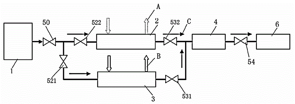
[0022] Embodiment 1 of the passenger car of the present invention: includes a liquefied gas cooling energy air-conditioning device, the liquefied gas cooling energy air-conditioning device mainly includes two refrigeration systems, the first is a vaporization refrigeration system, and the second is a traditional refrigeration system, wherein the vaporization refrigeration system is mainly It uses the principle that liquefied gas needs to be vaporized and absorbed heat in the process of being transported to the engine, and realizes refrigeration by using the cold energy released by liquefied gas, such as figure 1 Shown is a schematic diagram of the gas supply pipeline of a passenger car. The liquefied gas gas storage tank 1 can transport the gas to the engine 6 for combustion and provide kinetic energy to the engine through the main gas transmission pipeline. The main gas transmission pipeline includes the first gas transmission pipe arranged in parallel The first gas pipeline i...

Embodiment 2

[0026] Embodiment 2 of the passenger car of the present invention: the difference from Embodiment 1 is that the heat exchange device adopts a carburetor.

[0027] Embodiment 3 of the passenger car of the present invention: the difference from Embodiment 1 is that the heat exchange device is a heat exchange box composed of heat exchange coils.

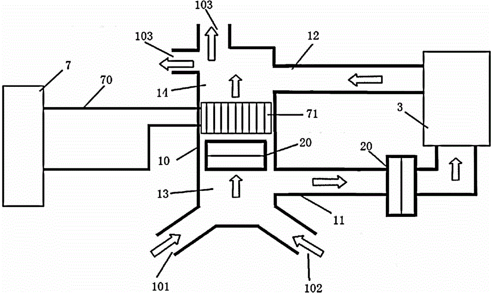
[0028] Embodiments of the liquefied gas cold energy air conditioner of the present invention: as Figure 1-2 As shown, its specific structure is the same as that of the liquefied gas cooling energy air-conditioning device in the above passenger car embodiment, and will not be repeated here.


PUM


Abstract

The invention provides an air-conditioning unit utilizing cold energy of liquefied fuel gas and a car. The air-conditioning unit utilizing cold energy of liquefied fuel gas comprises a main pipeline for fuel gas transmission communicated with a fuel gas storage tank and an engine and comprises a vaporized refrigerating system comprising an ambient air vaporizer arranged on the main pipeline for fuel gas transmission and further comprises a first air-supply pipeline used for conducting heat exchange with the ambient air vaporizer.When the air-conditioning unit utilizing cold energy of liquefied fuel gas is put in use, thermal air flow directly enters a vaporizing device by means of a vaporizing and refrigerating air inlet pipeline to conduct heat exchange with liquefied fuel gas. Therefore, vaporization of liquefied fuel gas is achieved and cold air flow is formed by decreasing temperature of thermal air flow. The cold air flow enters into the car by means of a vaporizing and refrigerating air outlet pipeline so that the refrigeration purpose is fulfilled. With the refrigeration mode, loss of cold energy is small due to heat exchange at a time. The overall air-conditioning unit has an easy structural form so that manufacturing cost is reduced.

Description

technical field [0001] The invention relates to the technical field of vehicle air treatment equipment, in particular to a liquefied gas cold energy air conditioner and a passenger car. Background technique [0002] With the increasingly serious environmental pollution and energy crisis, energy conservation and emission reduction has become the theme of today's human society. Especially in the field of automobiles, the development of energy-saving and environment-friendly automobiles has become the main research direction of every automobile manufacturer. With the advancement of technology and the improvement of quality of life, automotive air conditioning systems have become standard equipment for vehicles. When the traditional vehicle-mounted air-conditioning system works, the engine drives the compressor to work, and uses the gasification and heat absorption of the refrigerant to produce a cooling effect. However, the air-conditioning system greatly increases fuel consu...

Claims


Application Information

Patent Timeline
Patent Type & Authority Applications(China)
IPC IPC(8): B60H1/32
CPCB60H1/00328B60H1/32
Inventor 王印束王富生王兴赵利文赵玉东岳淑彪白学森
Owner ZHENGZHOU YUTONG BUS CO LTD
Why Eureka
Try Eureka