Heat pipe type heat energy recovery device

A heat energy recovery, heat pipe technology, applied in indirect heat exchangers, lighting and heating equipment, etc., can solve problems such as easy blockage of heat exchange plates, inability to put into production applications, and failure to achieve expected results.

Inactive Publication Date: 2015-08-26
韦华全 +1
View PDF9 Cites 2 Cited by
  • Summary
  • Abstract
  • Description
  • Claims
  • Application Information

AI Technical Summary

Problems solved by technology

However, due to the low heat transfer rate of the tube-and-tube heat exchanger and the plate heat exchanger, the heat exchange effect is poor, and the expected effect is not achieved, and the f

Method used


Image

  • Heat pipe type heat energy recovery device
  • Heat pipe type heat energy recovery device
  • Heat pipe type heat energy recovery device

Examples


Embodiment Construction

[0021] Below in conjunction with accompanying drawing, preferred embodiment of the present invention is described in further detail:

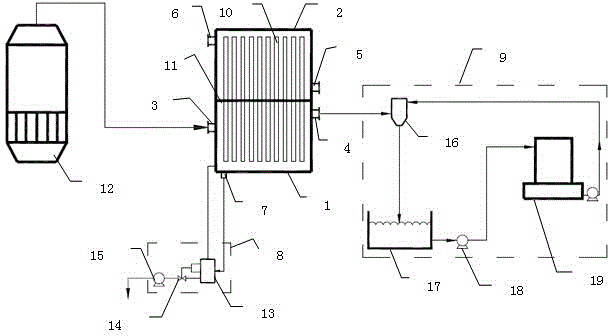
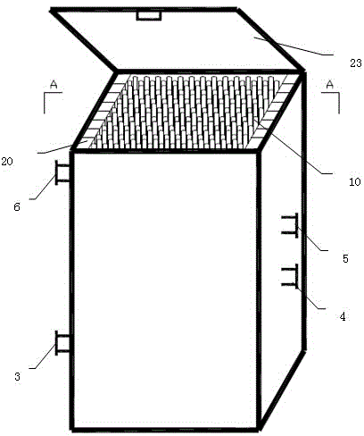
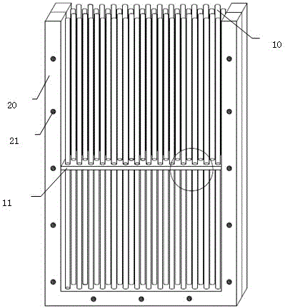
[0022] to combine Figures 1 to 3 , a heat pipe type heat energy recovery device, including a condensation box, a group of heat pipe assemblies 20 are vertically sleeved in the condensation box, and each heat pipe assembly 20 includes a U-shaped outer frame, and a partition arranged transversely on the inner wall of the outer frame 11 and the gravity heat pipe 10 vertically passing through the partition 11, the lower space of the partition 11 is the steam chamber 1, the upper space of the partition 11 is the condensation chamber 2, and the side wall of the steam chamber 1 has a lower inlet 3 , the lower outlet 4 and the drain 7, the side wall of the condensation chamber 2 has an upper inlet 5 and an upper outlet 6; the lower inlet 3 is connected to the final effect evaporation tank 12, and the lower outlet 4 is connected to the cooling system 9...


PUM


Abstract

The invention discloses a heat pipe type heat energy recovery device which comprises a condensing box. A set of heat pipe assemblies is vertically arranged in the condensing box in a sleeved mode. Each heat pipe assembly comprises a U-shaped outer frame, a separation plate horizontally arranged on the inner wall of the outer frame and a gravity heat pipe vertically penetrating through the separation plate. The space below each separation plate forms a steam chamber, and the space above each separation plate forms a condensing chamber. A lower inlet, a lower outlet and a drain outlet are formed in the side wall of each steam chamber, and an upper inlet and an upper outlet are formed in the side wall of each condensing chamber. The lower inlets are connected with a tail effect evaporation tank, the lower outlets are connected with a cooling system, and the drain outlets are connected with an equipressure drainage assembly. Heat in juice steam is used for heating sugarcane juice at other procedures, vacuum is generated at the same time, sugarcane juice in the tail effect evaporation tank can conveniently boil, a large amount of cooling water is saved, and the problem that the gravity heat pipes are blocked is avoided.

Description

technical field [0001] The invention relates to the field of heat energy recovery, in particular to a heat pipe type heat energy recovery device. Background technique [0002] At present, sugar enterprises generally adopt the relatively energy-saving five-effect pressure-vacuum evaporation thermal scheme to concentrate sugar juice. The final-effect vacuum juice vapor is sucked through a water jet condenser, mixed and condensed directly with water to form a vacuum of -0.075 to 0.078 MPa, which meets the production requirements. According to the process requirements, spray condensed water for cooling and recycling to reduce effluent. However, a large amount of cooling water is required, and the resulting vacuum pressure is unstable. [0003] In order to recycle the heat energy of low-temperature and low-pressure steam, many sugar enterprises and scientific researchers have tried to use shell-and-tube heat exchangers and plate heat exchangers to heat sugarcane juice to recover...

Claims


Application Information

Patent Timeline
IPC IPC(8): F28D15/02
Inventor 韦华全覃晔
Owner 韦华全
Why Eureka
Try Eureka