Preparation method for evaporating pipe of flooded evaporator

A flooded evaporator and evaporation tube technology, which is applied in the field of evaporation tube preparation, can solve the problems not given, and achieve the effects of improving nucleate boiling, improving heat transfer coefficient, and good size uniformity

Inactive Publication Date: 2017-11-10
JIANGSU CUILONG PRECISION COPPER TUBE CORP
View PDF26 Cites 0 Cited by
  • Summary
  • Abstract
  • Description
  • Claims
  • Application Information

AI Technical Summary

Problems solved by technology

However, this patent scheme does not give the enlightenment of the specific technical connotation of copper powder sintering on the outside of the tube, and the copper powder is sintered at high temperature to form an integrated structure with the tube

Method used


Image

  • Preparation method for evaporating pipe of flooded evaporator
  • Preparation method for evaporating pipe of flooded evaporator

Examples


Embodiment 1

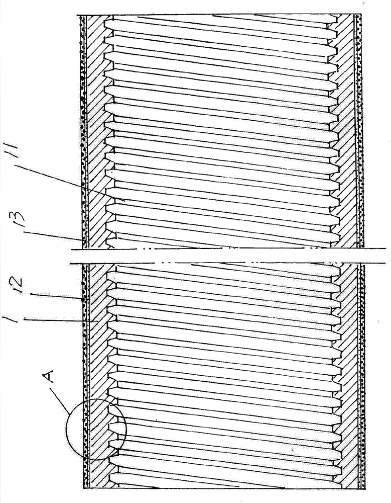
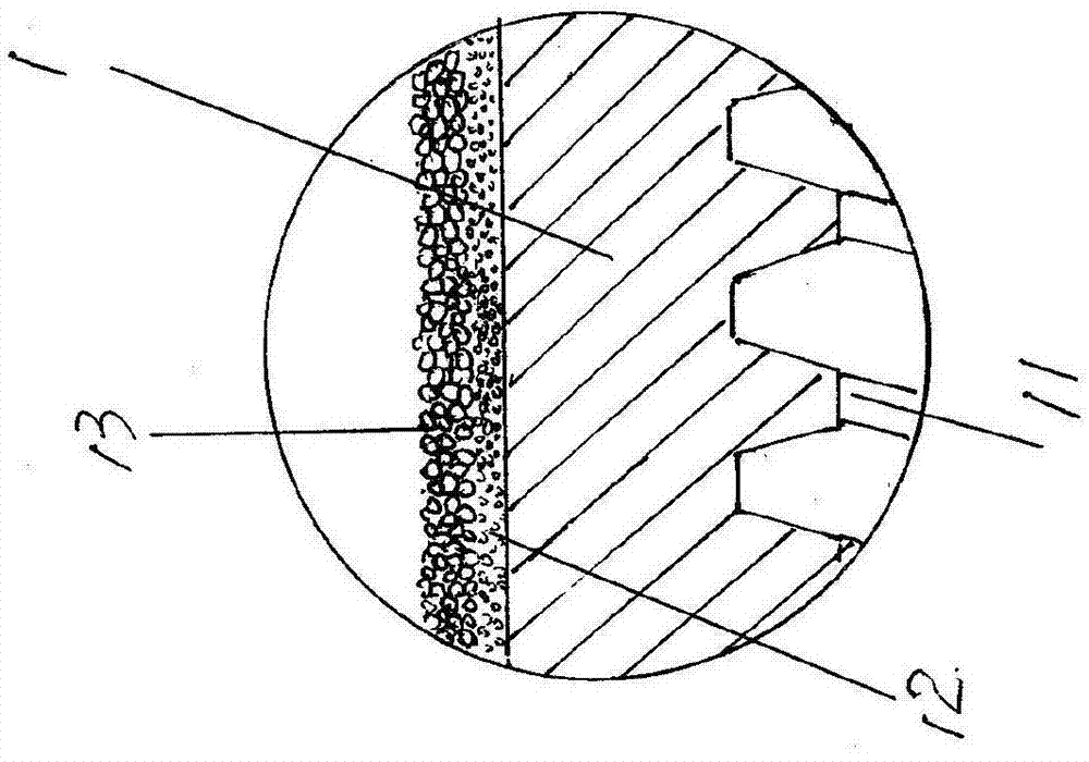
[0026] figure 1 with figure 2 The preparation method of the evaporation tube of the shown flooded evaporator comprises the steps:

[0027] A) Preliminary preparation, first rolling out the spiral inner teeth 11 on the inner wall of the copper pipe 1, and then ultrasonically cleaning and drying the inner and outer surfaces of the copper pipe 1;

[0028] B) Sintering, first place a stainless steel tube over the copper tube 1 obtained in step A), keep a gap with a width of 0.2 mm between the stainless steel tube and the outer wall of the copper tube 1, and fill the gap of 0.2 mm The fine copper powder particles with a mesh number of 1000, that is, passing through a 1000-mesh sieve, are then introduced into the sintering furnace for sintering under the protection of nitrogen protective gas. The sintering temperature is 950°C, and the sintering time is 25 minutes. After leaving the sintering furnace, cool and pull out the stainless steel tube , on the outer wall of the copper tu...

Embodiment 2

[0032] Only change the gap width in step B) to 0.22mm, change the mesh number of fine copper powder particles to 800 mesh, change the sintering temperature to 800°C, change the sintering time to 35min, and change the capillary structure layer of fine copper powder particles Change the thickness of 12 to 0.22mm; change the width of the gap in step C) to 0.4mm, change the mesh number of coarse copper powder particles to 500 mesh, change the re-sintering temperature to 950°C, and change the re-sintering time to Change the thickness of the thick copper powder particle capillary structure layer 13 to 0.4 mm; change the temperature for further sintering in step D) to 950° C., and change the time for further sintering to 30 minutes. All the other are the same as the description to embodiment 1.

Embodiment 3

[0034]Only change the gap width in step B) to 0.18mm, change the mesh number of fine copper powder particles to 900 mesh, change the sintering temperature to 900°C, change the sintering time to 30min, and change the capillary structure layer of fine copper powder particles Change the thickness of 12 to 0.18mm; change the width of the gap in step C) to 0.38mm, change the mesh number of coarse copper powder particles to 400 mesh, change the re-sintering temperature to 850°C, and change the re-sintering time to Change the thickness of coarse copper powder particle capillary structure layer 13 to 0.38mm; change the temperature of further sintering in step D) to 800°C, and change the time of further sintering to 40min. All the other are the same as the description to embodiment 1.

[0035] The comprehensive heat transfer coefficient of the evaporation tube of the flooded evaporator obtained by the above implementations 1 to 3 can be improved by 50-100% compared with the rolled finn...


PUM

PropertyMeasurementUnit
Widthaaaaaaaaaa
Meshaaaaaaaaaa
Widthaaaaaaaaaa

Abstract

The invention discloses a preparation method for an evaporating pipe of a flooded evaporator. The preparation method comprises the steps that spiral internal teeth are rolled on the inner wall of a copper pipe, and then the inner surface and the outer surface of the copper pipe are cleaned and dried; the copper pipe is sleeved with a fine copper powder particle limiting pipe, introduced into a sintering furnace to be sintered with protective gas, discharged out of the sintering furnace and cooled, the fine copper powder particle limiting pipe is pulled away, and a fine copper powder particle capillary-structure layer is combined with the outer wall of the copper pipe; the fine copper powder particle capillary-structure layer is sleeved with a coarse copper powder particle limiting pipe, introduced into the sintering furnace to be sintered with protective gas, discharged out of the sintering furnace and cooled, the coarse copper powder particle limiting pipe is pulled away, a coarse copper powder particle capillary-structure layer is combined with the outer side of the fine copper powder particle capillary-structure layer, and a pipe blank is obtained; and the pipe blank is introduced into the sintering furnace to be sintered with protective gas, discharged out of the sintering furnace and cooled, and the evaporating pipe of the flooded evaporator is obtained. Thermal contact resistance between the copper pipe and the fine powder particle capillary-structure layer as well as between the copper pipe and the coarse powder particle capillary-structure layer is avoided, and the heat exchange performance is good; a heat transfer coefficient is increased; and the maximum effect of the thermal conductivity is achieved.

Description

technical field [0001] The invention belongs to the technical field of heat exchange tube preparation, and in particular relates to a method for preparing an evaporation tube of a flooded evaporator. Background technique [0002] As known in the industry, in the fields of refrigeration, air-conditioning engineering, and energy and power engineering, it is common to involve refrigeration system units and air-conditioning system units in which liquid evaporates on the outer surface of the tube bundle, and most of the large-scale central air-conditioning centrifugal units use flooded evaporators. Due to the good plasticity of copper material, copper tubes are usually used for flooded evaporator tubes. In order to increase the heat transfer area and increase the heat transfer coefficient, fins (usually called outer fins) are formed on the outer wall of the copper tube by extrusion rolling or welding, and inner fins are rolled on the inner wall of the copper tube. [0003] There...

Claims


Application Information

Patent Timeline
IPC IPC(8): B22F7/08B22F5/12
CPCB22F7/08B22F5/106
Inventor 陆明华张春明金莉雯
Owner JIANGSU CUILONG PRECISION COPPER TUBE CORP
Why Eureka
Try Eureka