Cylindrical structure gradual-change fin phase change heat accumulator

A gradient fin, phase change heat storage technology, applied in heat storage equipment, heat exchanger types, indirect heat exchangers, etc., can solve the problem of high thermal stress, low thermal conductivity, and low utilization rate of square heat storage containers. problems, to achieve the effect of improving heat storage effect, consistent heat transfer temperature difference, and increasing melting

Inactive Publication Date: 2015-08-26
NORTH CHINA ELECTRIC POWER UNIV (BAODING)
View PDF5 Cites 5 Cited by
  • Summary
  • Abstract
  • Description
  • Claims
  • Application Information

AI Technical Summary

Problems solved by technology

[0004] Aiming at the problems of low thermal conductivity and low utilization rate of the phase change material of the phase change heat accumulator and excessive local thermal stress of the square heat storage container, a phase change heat accumulator with cylindrical structure with gradual fins is proposed, including: upper end surface, storage Heat shell, annular fins, heat exchange tube bundles, phase change material, and bottom surface; the overall structure of the heat accumulator is cylindrical and arranged vertically; between the upper end surface and the bottom surface, multiple heat exchange tube bundles are vertically arranged in a circular array, The heat exchange tube bundles are parallel to each other and equally spaced; multiple annular fins are parallel to the upper end surface and the bottom surface, and are arranged horizontally between the upper end surface and the bottom surface. The annular fins of each stage are connected with all the heat exchange tube bundles to form a closed channel. The heat exchange fluid flows; the heat storage shell wraps the cylindrical space between the upper end surface and the bottom surface, and in the formed cylindrical space, the phase change material is stored in the remaining space except for the closed channel formed by the annular fins and the heat exchange tube bundle

Method used


Image

  • Cylindrical structure gradual-change fin phase change heat accumulator
  • Cylindrical structure gradual-change fin phase change heat accumulator
  • Cylindrical structure gradual-change fin phase change heat accumulator

Examples


Embodiment Construction

[0016] The embodiments will be described in detail below in conjunction with the accompanying drawings.

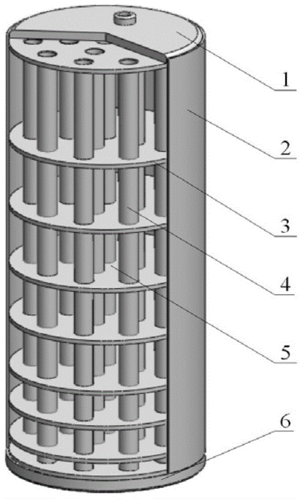
[0017] like figure 1 As shown, the present invention is composed of an upper end surface 1 , a heat storage shell 2 , an annular fin 3 , a heat exchange tube bundle 4 , a phase change material 5 and a bottom surface 6 . The overall structure of the heat accumulator is cylindrical and arranged vertically. The annular fins 3 are arranged horizontally, and the annular fins 3 of each stage are integrated, and the interfaces of the heat exchange tube bundles 4 are equidistantly arranged according to the specific requirements of heat storage. The heat exchange tube bundles 4 are vertically arranged parallel to each other and equally spaced. A heat exchange fluid flows in the heat exchange tube bundle 4 . The phase change material 5 is stored between the annular fins 3 , and the fin spacing of the annular fins 3 decreases continuously along the direction in which the heat tran...


PUM


Abstract

The invention belongs to the technical field of heat accumulation, and particularly relates to a cylindrical structure gradual-change fin phase change heat accumulator. The heat accumulator comprises an upper end face (1), a heat accumulation shell (2), annular fins (3), heat exchange pipe bundles (4), a phase change material (5) and a bottom face (6). The heat exchange pipe bundles are vertically arranged between the upper end face and the lower end face in a peripheral array mode and are arranged at equal intervals in parallel. The annular fins are parallel to the upper end face and the lower end face and horizontally arranged between the upper end face and the lower end face, each level of annular fins is connected with all the heat exchange pipe bundles to form a sealed channel, and heat exchange fluid flows in the channel. The heat accumulation shell wraps a cylindrical space between the upper end face and the bottom face, and the phase change material is stored in the cylindrical space. The intervals of the annular fins are changed gradually, the more the annular fins are close to the bottom face, the intervals are smaller, the heat exchange temperature difference of the heat accumulator more tends to be consistent, and the phenomena that the phase change material is partially excessively hot, and the heat stress of a heat accumulation container is excessively high are reduced.

Description

technical field [0001] The invention belongs to the technical field of heat storage, in particular to a phase-change heat accumulator with cylindrical structure and gradually changing fins. Background technique [0002] With the depletion of fossil fuels and the deterioration of the natural environment, finding alternative energy sources for sustainable development has become a major concern of many countries. Research on sensible heat, latent heat, and chemical reaction heat storage technologies can reduce the mismatch between intermittent energy supply and demand. Latent heat storage has the advantages of good performance, high reliability, high heat storage density and almost constant heat transfer temperature, but the low thermal conductivity of phase change materials limits the development of latent heat storage technology. [0003] During the heat storage process, since the heat exchange temperature difference between the heat exchange fluid and the phase change mater...

Claims


Application Information

Patent Timeline
Patent Type & Authority Applications(China)
IPC IPC(8): F28D20/02
CPCY02E60/14
Inventor 徐鸿飞杜小泽杨佳霖杨立军
Owner NORTH CHINA ELECTRIC POWER UNIV (BAODING)
Why Eureka
Try Eureka