
Sub-area fault diagnosis method for transformer station grounding network

A substation grounding grid and fault diagnosis technology, applied in the field of electric power information, can solve problems such as low reliability of results, less data, and complex algorithm structure.

Inactive Publication Date: 2015-08-26
SHANGHAI JIAO TONG UNIV +2
View PDF0 Cites 15 Cited by
  • Summary
  • Abstract
  • Description
  • Claims
  • Application Information

AI Technical Summary

Problems solved by technology

Some scholars have further studied the application of the new intelligent optimization algorithm in solving the fault diagnosis equation, and achieved certain results. However, due to the high degree of ill-conditioning of the fault diagnosis equation, the data that can be obtained is relatively small, and the reliability of the results obtained by the above method still low
In order to improve the reliability of the diagnosis, the researchers proposed to layer and reduce the network at the accessible nodes according to the structure of the grounding grid to obtain the intrinsic grounding grid containing only the accessible nodes, and further use the method of layer-by-layer tracing to determine each The resistance of the branches is clearly hierarchical, which reduces the ill-conditioned degree of the diagnostic equation, but there are still many uncertain branches, and the algorithm structure is complex and the calculation amount is very large
[0004] Since the grounding leads of the equipment in the substation are limited, the grounding grid fault diagnosis equation constructed by any method is an underdetermined equation, and the obtained results are uncertain

Method used


Image

  • Sub-area fault diagnosis method for transformer station grounding network
  • Sub-area fault diagnosis method for transformer station grounding network
  • Sub-area fault diagnosis method for transformer station grounding network

Examples


Embodiment 1

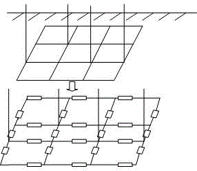
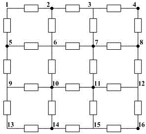
[0152] image 3 Shown is a substation grounding grid network topology diagram, with 16 nodes, of which 2, 4, 5, 7, 8, 10, 11, 14, and 16 are accessible nodes. The specific decomposition of the grounding grid can be found in this article Figure 4-8 . Under normal conditions, the nominal resistance value of each branch is 60mΩ, and there are three existing branches that have failed, as follows: No. 1-2 branch becomes 300mΩ, No. 7-8 branch becomes 600mΩ, No. 11-15 The branch becomes 900mΩ.

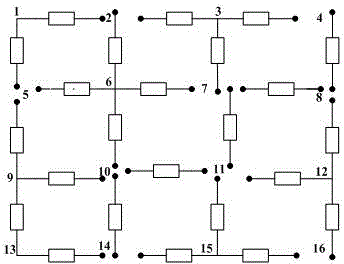
[0153] Figure 4-8 They are the quasi-meta-block, meta-block, meta-network, accessible grounding grid, and intrinsic grounding grid obtained by hierarchical reduction of the topological structure of the grounding grid, Figure 9 It is the area diagram of grounding network division. According to the process of reducing the quasi-element block to the intrinsic grounding grid, each branch in the intrinsic grounding grid is traced up to the grounding grid layer by layer, Figure 8 Table 1 s...


PUM


Abstract

A sub-area fault diagnosis method for a transformer station grounding network aims at a given grounding network design topology structure and performs layered reduction on the grounding network design topology structure. The sub-area fault diagnosis method comprises the steps of calculating nominal value parameters of branch resistors according to original designing data, selecting a common node, generating an associated matrix A and a branched admittance matrix Y; building a simulated circuit model, applying a DC source excitation I0 between nodes i and j which are selected in the circuit; testing the voltage Uij of a selected accessible node, and obtaining a port resistance Rij between the nodes i and j; after the grounding network fails and the measured port resistance between the nodes i and j is changed to R'ij, comparing the measured port resistance with the accessible port resistance in the normal state of the grounding network, and obtaining a port resistance difference vector deltaRij, and establishing a fault diagnosis equation set according to a fault simulation model; solving the fault diagnosis equation set and acquiring a final calculation result; and according to a solving result, calculating a nominal value multiple which corresponds with a branch resistance value after an intrinsic grounding network fails, and determining a fault condition.

Description

technical field [0001] The invention relates to the technical field of electric power information, in particular to a sub-area fault diagnosis method for a substation grounding grid. Background technique [0002] The substation grounding grid is usually laid horizontally with flat steel or round steel, arranged in long or square holes, buried 0.6-0.8m underground, and its area is roughly the same as that of power plants and substations. The grounding grid is very important to the safe operation of electrical equipment. In recent years, the number of substation operation accidents caused by the degradation of the electrical performance of the grounding grid has increased year by year. Among them, the corrosion, fracture or missing welding of the conductors are potential factors that cause the degradation of the grounding performance. In the event of a grounding short circuit fault in the power system, it will cause the local potential difference of the ground grid itself and ...

Claims


Application Information

Patent Timeline
Patent Type & Authority Applications(China)
IPC IPC(8): G01R31/02G01R31/08
CPCY04S10/52
Inventor 郑益慧李立学王昕蓝文昊陈洪涛张明海韩长海
Owner SHANGHAI JIAO TONG UNIV
Learn More