
A Method for Simulation and Analysis of Polarization of Photolithography Projection Objective Lens

A technology of simulation analysis and lithography projection, which is used in microlithography exposure equipment, photolithography process exposure devices, etc., to achieve the effects of reduced cost, low cost and convenient simulation conditions

Inactive Publication Date: 2017-06-27
INST OF OPTICS & ELECTRONICS - CHINESE ACAD OF SCI
View PDF10 Cites 0 Cited by
  • Summary
  • Abstract
  • Description
  • Claims
  • Application Information

AI Technical Summary

Problems solved by technology

The resolution of the image applied to the photoresist layer increases as the numerical aperture (NA) of the projection objective lens increases, as does the angle of incidence of the light rays in the optical system. Pure geometric ray tracing calculates the aberrations The method is difficult to meet the accuracy requirements, and the polarization aberration caused by the polarization of the system must be considered

Method used


Image

  • A Method for Simulation and Analysis of Polarization of Photolithography Projection Objective Lens
  • A Method for Simulation and Analysis of Polarization of Photolithography Projection Objective Lens
  • A Method for Simulation and Analysis of Polarization of Photolithography Projection Objective Lens

Examples


Embodiment 1

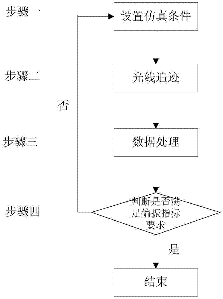
[0058] Step 1: Set the simulation conditions, where the input polarization mode selects linearly polarized light, the input beam polarization degree is 99.7%, the polarization state description method is set to Stokes vector, the loading film system (MgF2 single-layer film), and the material birefringence characteristics Load, select the field of view (0, 0) field of view;

[0059] Step 2: Ray tracing, where the number of traced rays is set to 1 million, and the polarization mode is turned on;

[0060] Step 3: Data processing. Obtain corresponding data through the compiled macro language file, including polarization type, polarization direction, intensity in X and Y directions, and degree of polarization. The specific data are as follows:

[0061] Sides Ix Iy degree of polarization Polarization direction Polarization type Object surface 0.99850 0.00150 0.99700 -90 0 1 0.94707 0.00143 0.99698 -90 0 2 0.89829 0.00137 0.99695 -90 0 ...


PUM

PropertyMeasurementUnit
degree of polarizationaaaaaaaaaa
refractive indexaaaaaaaaaa

Abstract

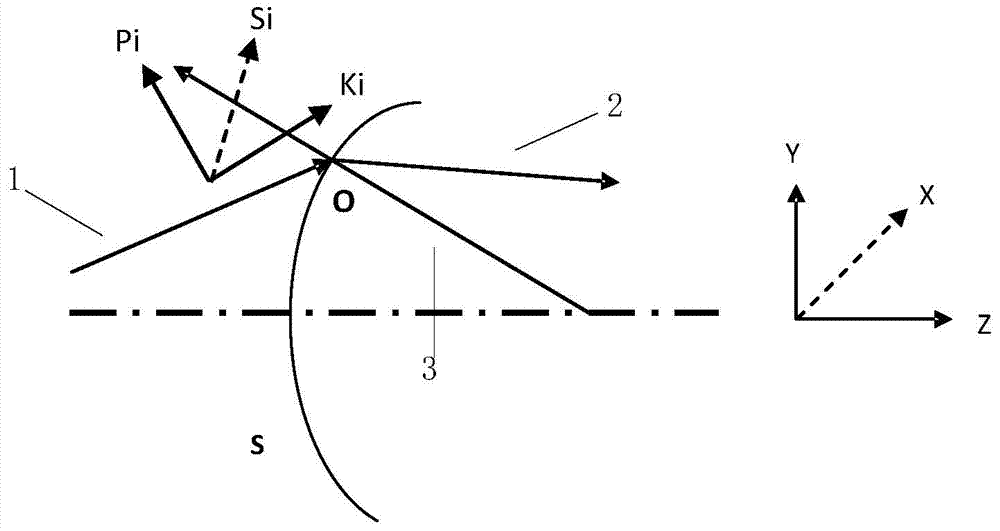
The invention provides a polarization simulation analysis method of a lithography projection objective lens, which solves whether the degree of polarization of an input polarized beam in high NA lithography technology meets the index requirement of a lithography exposure system after being acted on by a lithography projection objective lens. The polarization simulation analysis method mainly includes four steps of setting simulation conditions, ray tracing, data processing, and result judgment. The data obtained through simulation analysis provides guidance and basis for film system design, material property selection, and lithography projection objective optical system design. The polarization analysis method is based on Fresnel reflection and transmission theory, ray tracing and CODEV software, and has the advantages of real-time, intuitive, simple operation, convenient modification of simulation conditions, and low cost.

Description

technical field [0001] The invention relates to a polarization simulation analysis method, in particular to a polarization simulation analysis in a lithography projection objective lens, and belongs to the technical field of lithography polarization. Background technique [0002] Since the optical projection exposure technology was born in 1978, it has experienced several technological development stages such as g-line, i-line, 248nm, and 193nm. In just a few decades since its appearance, integrated circuits related to optical projection exposure technology have experienced several stages of development, such as small-scale, ultra-large-scale and extremely large-scale, strongly driven by the process of social informatization. Large-scale integrated circuits have become the cornerstone of the development of high-tech fields. From the aerospace fields such as satellites and rockets to the defense fields of radar and laser-guided missiles, as well as various fields of people's ...

Claims


Application Information

Patent Timeline
Patent Type & Authority Patents(China)
IPC IPC(8): G03F7/20
Inventor 范真节邢廷文林妩媚廖志杰张海波
Owner INST OF OPTICS & ELECTRONICS - CHINESE ACAD OF SCI
Learn More