New energy power station dynamic reactive power compensation equipment application method and device

A technology of compensation equipment and compensation devices, applied in reactive power compensation, reactive power adjustment/elimination/compensation, AC network voltage adjustment, etc., can solve problems such as operation stability and power quality problems of compensation equipment in new energy power stations, and achieve Reduce single-phase ground capacitive current, improve stability, and be conducive to the effect of stable operation

Inactive Publication Date: 2015-08-26
GANSU ELECTRIC POWER DESIGN INST
View PDF7 Cites 8 Cited by
  • Summary
  • Abstract
  • Description
  • Claims
  • Application Information

AI Technical Summary

Problems solved by technology

[0006] The technical problem to be solved by the present invention is to provide an application method of dynamic reactive power compensation equipment for new energy power stations. Another technical problem to be solved by the present invention is to provide an application device for dynamic reactive power compensation equipment for new energy power stations; Operation stability and power quality problems of power station compensation equipment

Method used


Image

  • New energy power station dynamic reactive power compensation equipment application method and device
  • New energy power station dynamic reactive power compensation equipment application method and device
  • New energy power station dynamic reactive power compensation equipment application method and device

Examples


Embodiment Construction

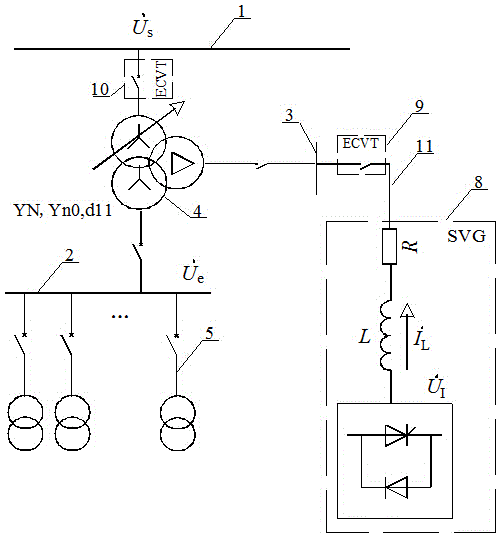
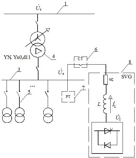
[0022] For the traditional installation method of dynamic reactive power compensation equipment in new energy power stations, see figure 2 : A plurality of new energy collection lines 5 are connected in parallel to the bus bar 3 on the low-voltage side of the step-up transformer, and the bus bar 3 on the low-voltage side of the step-up transformer is connected to the low-voltage side of the step-up transformer 4; and the dynamic reactive power compensation device 8 is connected to the step-up transformer A conventional current transformer 6 is installed on the connection line between the dynamic reactive power compensation device 8 and the low-voltage side bus 3 of the step-up transformer, and the low-voltage side bus 3 of the step-up transformer is also connected with a conventional voltage transformer 7. The high voltage side of the transformer 4 is connected to the bus bar 1 on the high voltage side of the step-up transformer. The traditional new energy power plant dynamic...


PUM


Abstract

The invention discloses a new energy power station dynamic reactive power compensation equipment application method. The improved content is as follows: (1) the dynamic reactive power compensation equipment is connected onto a low voltage-side bus of a three-winding boost transformer, the middle voltage side of the three-winding boost transformer is connected with gathered new energy electric power, and the two are isolated via the transformer; (2) voltage at the high voltage side of the new energy power station serves as reactive power needed by a calculation system for calculating reference voltage and control target voltage; and (3) a novel electronic current voltage combined transformer is applied to a measurement control system for the dynamic reactive power compensation equipment. In view of problems of poor operation stability of the new energy power station and disqualified electric power quality, a dynamic reactive power compensation configuration technology which can be applied to grid-connected power generation of the new energy power station and meet grid requirements is brought forward, a dynamic reactive power compensation equipment mounting site is changed, the new energy collecting system and the reactive power compensation equipment can be effectively isolated, the problems of operation stability of the new energy power station compensation equipment and electric power quality can be solved, and operation stability of the reactive power compensation equipment is improved.

Description

technical field [0001] The invention relates to the technical field of installation methods and control strategies of new energy power grids, in particular to a method for applying dynamic reactive power compensation equipment in new energy power stations, and the invention also relates to an application device for dynamic reactive power compensation equipment in new energy power stations. Background technique [0002] The grid-connected power and voltage of wind farms and photovoltaic power plants fluctuate frequently, and when the grid fails and causes voltage drops, it must have low-voltage ride-through capability. In order to reduce the impact on the grid, reactive power compensation equipment in new energy power plants as the main source of reactive power , must have sufficient reactive power adjustment capability and response speed to meet the reactive power compensation needs of the system. Therefore, the dynamic reactive power compensation equipment SVG (Static Var G...

Claims


Application Information

Patent Timeline
Patent Type & Authority Applications(China)
IPC IPC(8): H02J3/18H02J3/16H02J3/38
CPCY02E40/30
Inventor 吴兴全王利平姚天亮吴丽魏刚李秋鹏瞿继平李学庆
Owner GANSU ELECTRIC POWER DESIGN INST
Why Eureka
Try Eureka