Vehicle-mounted charging device

A vehicle charging and circuit technology, applied in circuit devices, battery circuit devices, output power conversion devices, etc., can solve the problems of complex circuit design, high quality, and high energy loss.

Active Publication Date: 2015-08-26
BEIJING BORGWARD AUTOMOBILE CO LTD
View PDF4 Cites 4 Cited by
  • Summary
  • Abstract
  • Description
  • Claims
  • Application Information

AI Technical Summary

Problems solved by technology

[0006] For this reason, the technical problem to be solved by the present invention lies in the disadvantages of using a transformer in the insulated DC / DC conversion circuit of the existing on-board charging system, such as large mass, complicated circuit design, high energy loss, and high manufacturing cost. An on-board charging device that replaces the transformer for energy conversion

Method used


Image

  • Vehicle-mounted charging device
  • Vehicle-mounted charging device
  • Vehicle-mounted charging device

Examples


Embodiment 1

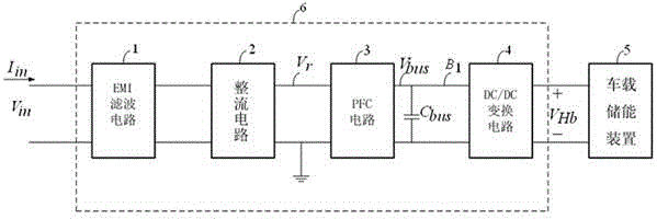
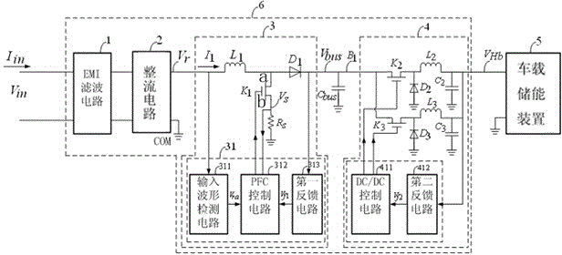
[0036] In this embodiment, a vehicle charging device is provided, such as figure 2 and image 3 As shown, it includes an electromagnetic interference (EMI) filter circuit 1, a rectifier circuit 2, a power factor compensation circuit 3, a DC / DC conversion circuit 4 and a vehicle-mounted energy storage device 5 connected in sequence, and the DC / DC conversion circuit 4 includes a switch circuit, and The DC / DC control circuit 411 connected to the control end of the switch circuit and the second feedback circuit 412 connected to the output end of the switch circuit, the output end of the second feedback circuit 412 is connected to the input end of the DC / DC control circuit 411, and the switch circuit includes a switch K 2 , inductance L 2 and capacitance C 2 , switch K 2 , inductance L 2 After being connected in series as the output terminal of the switch circuit, the capacitor C 2 One end of it is connected to the output end, and the other end is grounded.

[0037] In this...

Embodiment 2

[0055] On the basis of the above-mentioned embodiment 1, the on-board charging device of the embodiment of the present invention adds a current feedback circuit, such as Figure 5 As shown, a current feedback circuit is also included, and the current feedback circuit includes a current detection circuit 413 respectively connected to the output terminal of the DC / DC conversion circuit 4 and the input terminal of the DC / DC control circuit 411 . The current detection circuit 413 is for the current output by the DC / DC conversion circuit 4, that is, for the inductance L 2 or inductance L 3 The output current is sampled, and the sampled signal is input to the DC / DC control circuit 411 . In this way, both the voltage sampling closed-loop circuit: the second feedback circuit 412 and the current closed-loop sampling circuit: the current detection circuit 413 are included in the DC / DC conversion circuit 4. This structure can ensure that the DC / DC conversion circuit 4 can output The st...


PUM


Abstract

The invention discloses a vehicle-mounted charging device, which belongs to the technical field of charging and power supply. The vehicle-mounted charging device comprises a filter circuit, a rectifier circuit, a power factor compensation circuit, a DC / DC conversion circuit and a vehicle-mounted energy storage device, wherein the DC / DC conversion circuit comprises a switch circuit, a DC / DC control circuit connected with the control end of the switch circuit and a second feedback circuit connected with the output end of the switch circuit; the output end of the second feedback circuit is connected with the input end of the DC / DC control circuit; the switch circuit comprises a switch K2, an inductor L2 and a capacitor C2; the switch K2 and the inductor L2 are serially connected to serve as the output end of the switch circuit; and one end of the capacitor C2 is connected with the output end and the other end is grounded. Technical problems of large electromagnetic interference and much energy loss as the prior vehicle-mounted charging device commonly uses a transformer are solved, the switch circuit is adopted for outputting charging voltage, energy loss is low, and the charging efficiency is high.

Description

technical field [0001] The invention relates to the technical field of charging and power supply, in particular to a vehicle charging device. Background technique [0002] The existing on-board charging system generally adopts the technical route of filter circuit, AC / DC rectifier circuit, power factor compensation (PFC) circuit, isolated DC / DC conversion circuit and integrated control circuit. It mainly adopts rectification technology and DC / DC charging technology. [0003] like figure 1 It shows the schematic diagram of the existing on-board charging system. The AC220V voltage passes through the filter circuit to filter out the interference of the high-frequency pulse of the external power grid on the on-board charging system, and then outputs a relatively smooth primary current and voltage through the rectifier circuit and the power factor compensation (PFC) circuit. , and finally through the insulating DC / DC conversion circuit to output the secondary DC voltage and cur...

Claims


Application Information

Patent Timeline
Patent Type & Authority Applications(China)
IPC IPC(8): H02J7/10H02M3/155H02M1/44H02M1/12H02M1/42
CPCY02B70/10
Inventor 杨卓左从兵熊丽满王荣华
Owner BEIJING BORGWARD AUTOMOBILE CO LTD
Why Eureka
Try Eureka