Component of a fuel injection system

A fuel injection system and component technology, which is applied in the direction of fuel injection pumps, fuel injection devices, special fuel injection devices, etc., can solve problems such as surface wear, and achieve high corrosion resistance, reduced corrosion tendency, and long service life. Effect

Inactive Publication Date: 2015-08-26
ROBERT BOSCH GMBH
View PDF5 Cites 1 Cited by
  • Summary
  • Abstract
  • Description
  • Claims
  • Application Information

AI Technical Summary

Problems solved by technology

Especially in metal substrates provided with a hard chromium coating, cracks in the cover layer lead to the accumulatio

Method used


Image

  • Component of a fuel injection system
  • Component of a fuel injection system
  • Component of a fuel injection system

Examples


Embodiment Construction

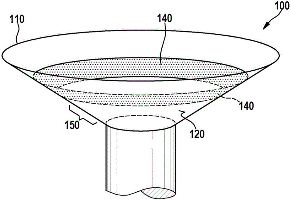
[0022] figure 1 A component 100 according to a first embodiment is shown, which is configured as a valve. Valve 100 is suitable, for example, for use as an injection valve in a fuel injector. The valve 100 has a substantially conical funnel 110 , wherein a valve seat 120 is formed centrally in the valve funnel 110 . Seat 120 serves as figure 1 The contact area of ​​the closing body, not shown, which either closes or opens the valve seat 120 depending on its position. In the section of the valve funnel 110 that is not actually directly mechanically loaded by the movement of the closing body, a sacrificial anode 140 is arranged above the active area 150 provided as a contact area for the closing body, which is formed there. Is the surface coating that surrounds annularly on the surface of the valve funnel. The surface coating consists of metals or metal compounds or alloys which are relatively inexpensive compared to the metals from which the valve 100 is formed.

[0023] ...


PUM


Abstract

The invention relates to a component (100) with at least two subcomponents made of metal. According to the invention, an alloy layer (140) is applied to the surface of a valve funnel (110) functioning as the subcomponent in a valve (100) functioning as the component, wherein the alloy layer (140) is made from a metal less noble than the valve funnel (110). The alloy layer (140) is arranged on a portion of the valve funnel (110) which is situated outside the direct mechanical action region (150) of the closing member (160) functioning as the second subcomponent, and is arranged as an annular portion running around the surface of the valve funnel (110), outside the mechanical action region of the closing member (160) relative to the closing member (160) resting in the valve seat (120) of the valve funnel in the closed state.

Description

technical field [0001] The invention relates to an assembly of a fuel injection system comprising at least two metallic subassemblies. Background technique [0002] In such assemblies consisting of multiple metallic subassemblies, corrosion processes often lead to wear of the subassemblies. These corrosion processes are caused by the different chemical potentials of the metals respectively used in the subassemblies. The potential differences occurring here of the individual subassemblies exert a force on the molecules of the respective ambient medium, which can be, for example, the fuel flowing through the injection valves used there in the case of so-called common rail injectors. Or the presence of oxygen in the external environment, said forces eventually cause corrosive decomposition processes leading to unwanted and premature wear of the components. [0003] From the prior art eg from Neidel's "Handbook of Metal Damage (Handbuch )", pp. 214 to 216, Carl Hanser Verlag...

Claims


Application Information

Patent Timeline
IPC IPC(8): F02M63/00F02M61/18F02M59/10F02M61/16
CPCF04B1/0426F02M2200/9053F02M2200/05F02M63/0031F02M63/0077F02M59/102F02M61/1886F02M61/166
Inventor B·曼克J·施特雷勒
Owner ROBERT BOSCH GMBH
Why Eureka
Try Eureka