Construction Ventilation Structure and Ventilation Volume Control Method of Highway Tunnel

A technology for road tunnels and control methods, which is applied in mine/tunnel ventilation, earthwork drilling, complex mathematical operations, etc. It can solve the problems of energy waste and high ventilation energy consumption, and achieve the effect of reducing energy consumption

Active Publication Date: 2017-03-15
SICHUAN DEPT OF TRANSPORTATION HIGHWAY PLANNING PROSPECTING & DESIGN RES INST
View PDF6 Cites 0 Cited by
  • Summary
  • Abstract
  • Description
  • Claims
  • Application Information

AI Technical Summary

Problems solved by technology

[0004] However, the applicant’s research found that in the tunnel construction project, the operating machinery at the face of the front end of the tunnel can be considered as centralized sewage discharge, and the operating machinery in the return air lane can be considered as uniform sewage discharge. distributed as figure 2 As shown, the wind speed from the face of the return airway to the tunnel opening is constant, and correspondingly, the concentration of CO and other pollutants in the return airway is distributed as image 3 As shown, the concentration of pollutants gradually increases from the face of the tunnel to the tunnel entrance, showing a triangular distribution. The pollutants at the entrance of the tunnel are the largest. To ensure that the concentration is within the design concentration range, the wind speed at the entrance of the return airway must reach a certain intensity, but the actual The concentration of pollutants in the front section of the tunnel is relatively small, and it does not require a high wind speed to meet the design standard. However, if the above ventilation method is used, the wind speed in the return air lane will be constant, which will undoubtedly cause a lot of energy waste, resulting in high ventilation energy consumption.

Method used


Image

  • Construction Ventilation Structure and Ventilation Volume Control Method of Highway Tunnel
  • Construction Ventilation Structure and Ventilation Volume Control Method of Highway Tunnel
  • Construction Ventilation Structure and Ventilation Volume Control Method of Highway Tunnel

Examples


Embodiment Construction

[0056] The present invention will be further described below in conjunction with the accompanying drawings.

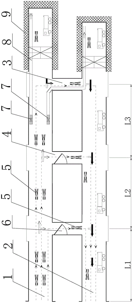
[0057] Such as figure 1 As shown, the highway tunnel construction ventilation structure disclosed in the present invention includes an air inlet lane 1 and an air return lane 2, the front end of the air inlet lane 1 and the air return lane 2 is a face 9, and the air inlet lane 1 and the air return lane The front section of the lane 2 is connected to the front section of the cross passage 3. The air inlet lane 1 is provided with a fan 5 facing the front end of the tunnel, and the return air lane 2 is provided with a fan 5 facing away from the front end of the tunnel. The front section of the cross passage 3 There is also at least one middle section cross passage 4 which is ventilated simultaneously with the front section cross passage 3 between the tunnel opening. The middle section cross passage 4 is connected between the air inlet lane 1 and the return air lane 2. F...


PUM


Abstract

The invention relates to the field of road tunnel construction and discloses a road tunnel construction ventilating structure and a ventilation control method thereof. The road tunnel construction ventilating structure comprises an intake roadway and a return roadway; the front end of each of the intake roadway and the return roadway is provided with a working face; a front transverse passage is communicated with the front of both the intake roadway and the return roadway; a fan facing the front end of a tunnel is disposed within the intake roadway; another fan opposite to the front end of the tunnel is disposed within the return roadway; at least one middle transverse passage all communicated with the front transverse passage is disposed between the front transverse passage and an opening of the tunnel; the middle transverse passages are connected between the intake roadway and the return roadway; each of the front transverse passage and the middle transverse passage is internally provided with one fan facing the return roadway. The road tunnel construction ventilating structure and the ventilation control method thereof have the advantages that power consumption can be greatly lowered at the premise of keeping the pollutant concentration in a designed range and intake of the transverse passages helps allow segmental control for the pollutant concentration of the return roadway.

Description

technical field [0001] The invention relates to the field of road tunnel construction, in particular to a road tunnel construction ventilation structure and a ventilation volume control method thereof. Background technique [0002] During the construction of a double-hole road tunnel or a road tunnel with a horizontal guide tunnel, the air volume required for tunnel construction ventilation is calculated, and the air volume required is controlled by the air volume required by the operating machinery in the tunnel. As the excavation distance increases, the transport vehicles in the tunnel The number of units gradually increases, leading to an increase in air demand and a gradual increase in ventilation energy consumption. The construction ventilation method needs to be converted from the initial single-head press-in ventilation to tunnel ventilation, that is, one tunnel is the air inlet lane, and the other tunnel is the return air lane. , Open the cross passage near the face ...

Claims


Application Information

Patent Timeline
Patent Type & Authority Patents(China)
IPC IPC(8): E21F1/00G06F17/11G06F17/16
Inventor 周仁强李玉文郑金龙林国进蔚艳庆王联田尚志李蔚磎韦远飞朱长安唐协
Owner SICHUAN DEPT OF TRANSPORTATION HIGHWAY PLANNING PROSPECTING & DESIGN RES INST
Why Eureka
Try Eureka