LED lamp

A technology for LED lamps and metal lamp caps, which is applied in the direction of lampshades, cooling/heating devices of lighting devices, lighting and heating equipment, etc. Incandescent light distribution effect and other problems, to solve the problem of LED heat dissipation, meet the requirements of aesthetics, simple processing and assembly

Inactive Publication Date: 2015-09-02
ZHEJIANG YANKON GROUP
View PDF10 Cites 5 Cited by
  • Summary
  • Abstract
  • Description
  • Claims
  • Application Information

AI Technical Summary

Problems solved by technology

However, in order to meet the light distribution requirements of existing LED lamps, the design of radiators and light-transmitting components is often quite cumbersome. On the one hand, this not only wastes heat dissipation materials, but also increases the difficulty of processing and assembling the radiators; On the one hand, although the heat dissipation performance and light distribution of the whole lamp have been improved through the cumbersome radiator, the light distribution effect of the traditional incandescent lamp cannot be achieved due to the limitation of size.
In addition, under the pressure of cost control, the existing LED lamps often sacrifice the heat dissipation performance of LED lamps, that is, the heat dissipation performance often fails to meet the requirements, which makes the temperature of the LED chip very high, which seriously affects the service life of the LED lamp

Method used


Image

  • LED lamp
  • LED lamp
  • LED lamp

Examples


Embodiment Construction

[0022] The present invention will be further described in detail below in conjunction with the accompanying drawings and embodiments.

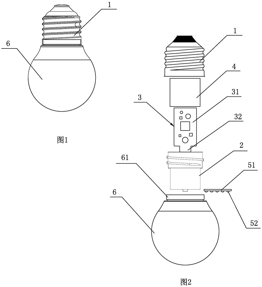
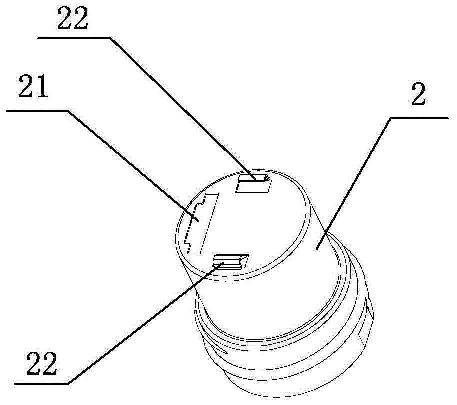
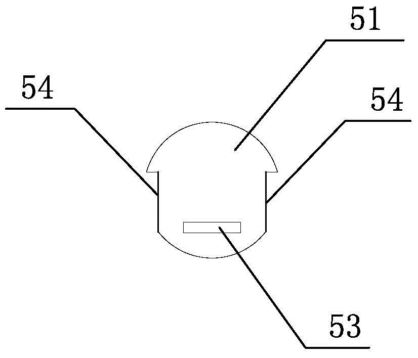
[0023] An LED lamp proposed by the present invention, as shown in the figure, includes a metal lamp cap 1, an aluminum heat sink 2, a driving power board 3, a hollow insulating protective cover 4 with an open bottom for protecting the driving power board 3, and a light source Components and PC bulb 6, the light source component is composed of a light source board 51 and several LED lamp beads 52 installed on the light source board 51; the aluminum heat sink 2 is hollow and the top is open, and the insulating protective cover 4 is set outside the drive power board 3 After the insulating protective cover 4 is set outside the driving power supply board 3, it is arranged in the aluminum forming radiator 2 through the top opening of the aluminum forming radiator 2, so that the insulating protective cover 4 is separated from the driving power supply ...


PUM


Abstract

The invention discloses an LED lamp. The LED lamp comprises a metal lamp base, an aluminum molded radiator, a driving power supply panel, a light source assembly and a PC bulb shell; the light source assembly is composed of a light source board and a plurality of LED lamp bulbs; the aluminum molded radiator is hollow and the top of the aluminum molded radiator is open; the driving power supply panel is arranged in the aluminum molded radiator via the top opening of the aluminum molded radiator; the light source board is connected to the outer bottom of the aluminum molded radiator; the light source board is connected with the driving power supply panel; the upper part of the aluminum molded radiator completely extends into the metal lamp base and is connected with the metal lamp base; the aluminum molded radiator is connected with the metal lamp base to form a heat dissipating assembly; the PC bulb shell is a pear-shaped light diffusion PC bulb shell; the mouth part of the PC bulb shell is connected with the inner side of the bottom of the metal lamp head so that the lower part of the aluminum molded radiator can be completely located in the PC bulb shell, and the light source board is close to the mouth part of the PC bulb shell; the LED lamp has the advantages of simple structure, small volume and simple manufacturing and assembly of the aluminum molded radiator, good heat dissipation property of the whole lamp due to heat dissipation via the lamp head, and good light distribution effect of the whole lamp.

Description

technical field [0001] The invention relates to a lamp, in particular to an LED lamp. Background technique [0002] With the rapid development of LED lighting technology, LED lights are a new type of energy-saving light source, and more and more places use LED lights as lighting sources. At present, the common LED lamps on the market usually include exposed radiators, power components, LED light source modules and light-transmitting components. Although the wide application of LED lamps saves resources to a great extent, it requires a large luminous angle, efficient heat dissipation performance and uniform light distribution. However, in order to meet the light distribution requirements of existing LED lamps, the design of radiators and light-transmitting components is often quite cumbersome. On the one hand, this not only wastes heat dissipation materials, but also increases the difficulty of processing and assembling the radiators; On the one hand, although the heat dis...

Claims


Application Information

Patent Timeline
Patent Type & Authority Applications(China)
IPC IPC(8): F21S2/00F21V3/02F21V3/04F21V23/00F21V29/503F21Y101/02
CPCF21V3/02F21V3/062F21V23/003
Inventor 宋永光卢文和
Owner ZHEJIANG YANKON GROUP
Why Eureka
Try Eureka