Monolayer multiporous foamed ceramic plate full-premix gas fuel burner
A foamed ceramic plate and porous foam technology, which is applied to gas fuel burners, burners, combustion methods, etc., can solve the problems of high energy consumption and pollutant emissions, uneven heating, and low heating efficiency.
- Summary
- Abstract
- Description
- Claims
- Application Information
AI Technical Summary
Problems solved by technology
Method used
Image


Examples
Embodiment 1
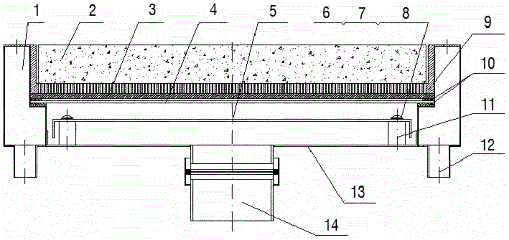
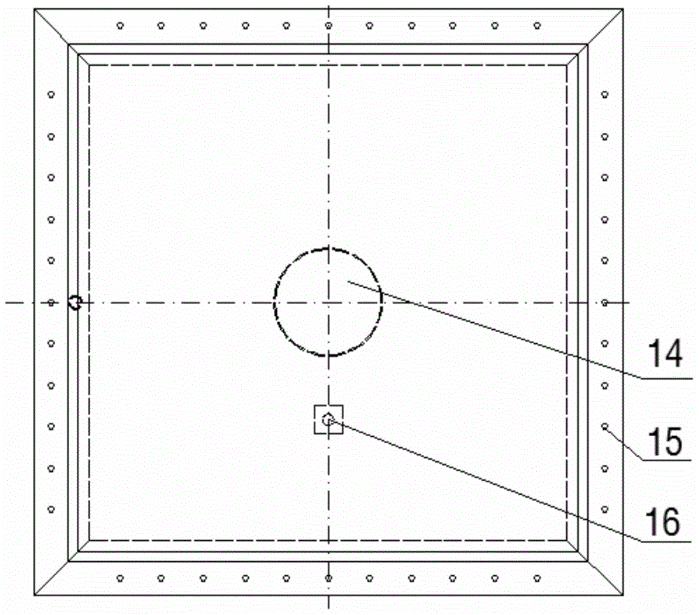
[0031] Embodiment 1: The present invention provides a single-layer porous ceramic foam board fully premixed gas fuel burner. This embodiment provides burners with four specifications. The cross-sectional shape of the burner is square, and the gas fuel uses natural gas. The burners of four specifications can be used alone, or can be arranged and combined in multiple groups, and can be applied to heat treatment furnaces in steel or machinery industries. The burner structure is as figure 1 , 2 shown. The main body of the burner includes cooling cavity 1, foam ceramic plate 2, heat-resistant steel bracket 3, top air distribution plate 4, bottom air distribution plate 5, screws 6, spring washers 7, flat washers 8, light Al 2 o 3 Honeycomb ceramic plate 9, rectangular annular gasket 10, support column 11, cooling air inlet 12, shell bottom plate 13, mixed gas inlet 14, cooling air outlet 15, inner tapered pressure pipe 16, wherein the burner housing is composed of The cooling ch...
Embodiment 2
[0046] Embodiment 2: The present invention provides a fully premixed gas fuel burner with a single-layer porous ceramic foam plate. Its structure is basically the same as that of Embodiment 1. The difference is that the specific geometric dimensions of the burner are taken according to Group 2 in Table 1. The material of the ceramic foam plate 2 is silicon carbide, the size of the ceramic foam plate is 200mm×200mm, and the cross-sectional shape of the burner is square.
[0047] Table 3 Burner gas and air flow when the air is not preheated
[0048]
[0049] The burners in this embodiment can be arranged and combined in multiple groups, and can be applied to heat treatment furnaces in steel or machinery industries. When several burner units are combined into a combined burner, when the burner units are replaced during use, the work of other burner units will not be affected.
Embodiment 3
[0050] Embodiment 3: The present invention provides a fully premixed gas fuel burner with a single-layer porous ceramic foam plate. Its structure is basically the same as that of Embodiment 1. The difference is that the specific geometric dimensions of the burner are taken according to Group 3 in Table 1. The size of the ceramic foam plate 2 is 300mm×300mm, and the cross-sectional shape of the burner is square. The burner can be arranged and combined in multiple groups and applied to heat treatment furnaces in the steel or machinery industry. When several burner units are combined into a combined burner, when the burner units are replaced during use, the work of other burner units will not be affected. The natural gas and air flow rates and combustion intensity of the burner are shown in Table 4.
[0051] Table 4 Burner gas and air flow when the air is not preheated
[0052]
[0053] Combustion effect: Air or gas fuel can not be preheated before entering the burner, and th...
PUM
| Property | Measurement | Unit |
|---|---|---|
| Average pore size | aaaaa | aaaaa |
| Average pore size | aaaaa | aaaaa |
| Width | aaaaa | aaaaa |
Abstract
Description
Claims
Application Information
 - R&D
- Intellectual Property
- Life Sciences
- Materials
- Tech Scout
- Unparalleled Data Quality
- Higher Quality Content
- 60% Fewer Hallucinations
Browse by: Latest US Patents, China's latest patents, Technical Efficacy Thesaurus, Application Domain, Technology Topic, Popular Technical Reports.
© 2025 PatSnap. All rights reserved.Legal|Privacy policy|Modern Slavery Act Transparency Statement|Sitemap|About US| Contact US: help@patsnap.com