Piezoelectric linear motor fused with shear piezoelectric actuator composite drive mode

A linear motor, driving mode technology, applied in the direction of piezoelectric effect/electrostrictive or magnetostrictive motors, generators/motors, electrical components, etc. , difficult and precise positioning and other problems, to overcome the effects of sub-micron and nano-precision positioning, simple structure and convenient preparation

Active Publication Date: 2015-09-02
PEKING UNIV +1
View PDF8 Cites 10 Cited by
  • Summary
  • Abstract
  • Description
  • Claims
  • Application Information

AI Technical Summary

Problems solved by technology

However, the existing L1B2 resonance mode linear piezoelectric motor has the following problems: In order to achieve fast and long-stroke linear motion of the piezoelectric motor, the piezoelectric transducer stator needs to work in the resonance mode, and the piezoelectric transducer Due to the harmonic vibration of the motor transducer at high frequency, the driving speed of the piezoelectric motor is too fast, making it difficult to achieve precise positioning at the submicron and nanoscale
However, its disadvantages are: driven by DC or AC voltage, piezoelectric actuators can only produce small strains or micro-displacements, or simple linear reciprocating displacements in the micro-nano range; they cannot produce cyclic elliptical motions and realize macroscopic continuous linear motion
However, piezoelectric motors working in high-frequency resonance modes are difficult to generate submicron and nanometer motions
Even if submicron or nanometer motion can be produced through some special control methods, it is generally at the cost of losing the driving force of the mover
The piezoelectric actuator can produce simple piezoelectric strain when working under DC voltage. Although it can produce submicron, nanometer micro displacement and large driving force, it cannot produce macroscopic continuous linear motion.

Method used


Image

  • Piezoelectric linear motor fused with shear piezoelectric actuator composite drive mode
  • Piezoelectric linear motor fused with shear piezoelectric actuator composite drive mode
  • Piezoelectric linear motor fused with shear piezoelectric actuator composite drive mode

Examples


Embodiment 1

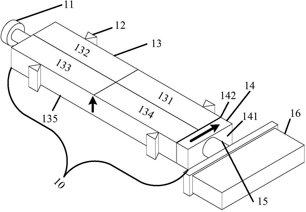
[0050] In the first embodiment, the piezoelectric motor transducer works in the first-order elongation (L1) and second-order bending (B2) modes. The structural size of the piezoelectric transducer 13 needs to be designed according to the condition that the resonant frequencies of the L1 and B2 modes are equal, and it is required that the L1 and B2 modes can be excited at the same time to design and divide the electrodes. During design, by adjusting the aspect ratio of the piezoelectric transducer 13, the frequencies of the L1 mode and the B2 mode are consistent. At the same time, if figure 1 As shown, the piezoelectric transducer 13 as a whole is polarized along the thickness direction (as figure 1 shown in ↑), and its upper surface electrode is divided into the first electrode area 131, the second electrode area 132, the third electrode area 133 and the fourth electrode area 134 four parts of the same rectangular area, the lower surface electrode is an integrated structure ...

Embodiment 2

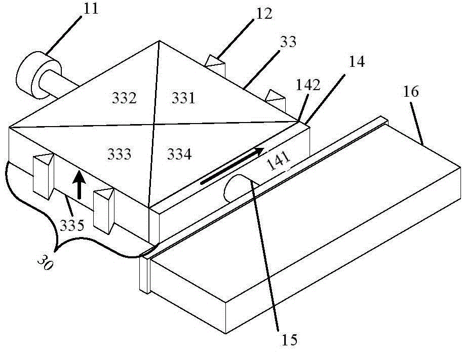
[0056] In the second embodiment, the piezoelectric motor works in the isomorphic first-order in-plane bending (B1B1) mode, and the piezoelectric transducer 33 needs to be designed as a square to ensure that the two isomorphic B1 modes are excited at the same operating frequency. At the same time, if image 3 As shown, the whole piezoelectric transducer 33 is polarized along the thickness direction (as image 3 shown in ↑), and the electrodes on the upper surface of the piezoelectric transducer 33 are divided into the first electrode area 331, the second electrode area 332, the third electrode area 333 and the fourth electrode area 334 along the diagonal line on the upper surface of the piezoelectric transducer 33. The four parts have the same area, and the bottom surface electrode is an integrated fifth electrode area 335 . The electrode areas 331, 332, 333 and 334 on the upper surface of the piezoelectric transducer 33 can be connected to the piezoelectric motor drive circui...

Embodiment 3

[0062] In the third embodiment, the piezoelectric motor transducer 53 works in the first-order in-plane diagonal bending (FDB) vibration mode of the same shape, and the piezoelectric transducer 53 needs to be designed as a square to ensure that the two same-shaped FDB modes operate at the same frequency. is excited. At the same time, if Figure 5 As shown, the piezoelectric transducer 53 as a whole is polarized along the thickness direction (as Figure 5 shown in ↑), and the upper surface electrode is divided into four parts of the same square area as the first electrode area 531, the second electrode area 532, the third electrode area 533 and the fourth electrode area 534, and the lower surface electrode has an integral structure The fifth electrode region 535 . The electrode areas 531, 532, 533 and 534 on the upper surface of the piezoelectric transducer 53 can be connected to the piezoelectric motor drive circuit to provide an AC input voltage of a specific frequency, and...


PUM


Abstract

The invention discloses a piezoelectric linear motor fused with a shear piezoelectric actuator composite drive mode and a preparation method thereof. The piezoelectric linear motor comprises a piezoelectric harmonic oscillation piezoelectric transducer, a shear piezoelectric actuator, a drive circuit, a slider, a friction head fixed to the shear piezoelectric actuator, and peripheral parts. The harmonic oscillation piezoelectric transducer and the shear piezoelectric actuator are tightly bonded together to form a composite piezoelectric drive stator. The friction head and the slider in a sliding assembly are in close contact. The harmonic oscillation piezoelectric transducer and the shear piezoelectric actuator are provided with an upper surface electrode and a lower surface electrode. The piezoelectric motor can be driven in a harmonic, direct-current or composite mode, can produce macroscopic continuous linear motion and sub-micron and nanometer motion, and can produce big driving force. The piezoelectric linear motor of the invention is simple in structure and convenient to make, and can be popularized and applied in the field of precision driving.

Description

technical field [0001] The invention relates to micro-nano precision drive technology for piezoelectric motors, in particular to a piezoelectric linear motor with a composite piezoelectric drive stator structure combined with a shear piezoelectric actuator and a micro-nano composite drive mode and a preparation method thereof. Background technique [0002] The piezoelectric motor uses the inverse piezoelectric effect of the piezoelectric element and the ultrasonic vibration of the elastic body to convert the micro-amplitude harmonic vibration of the elastic body into the macroscopic rotation or linear motion of the moving body through the friction between the stator and the mover. Thereby pushing the load directly. Piezoelectric motors have the advantages of compact structure and small volume, and have been widely used. A piezoelectric motor mainly includes a resonant piezoelectric transducer and a sliding assembly. The piezoelectric transducer is called the stator, and th...

Claims


Application Information

Patent Timeline
Patent Type & Authority Applications(China)
IPC IPC(8): H02N2/04H02N2/06
Inventor 董蜀湘慈鹏弘黄种团胡亦宁
Owner PEKING UNIV
Why Eureka
Try Eureka