Graphite substrate and manufacture method thereof, LED module and manufacture method thereof

A technology of a graphite substrate and a manufacturing method, applied in the field of LED lamps, can solve the problems of cracking of graphite sheets, restricting the use of substrates, unable to be made into flexible circuit boards, etc., and achieving the effects of simple manufacturing process and low production cost

Inactive Publication Date: 2015-09-02
RAYBEN TECH ZHUHAI
View PDF11 Cites 6 Cited by
  • Summary
  • Abstract
  • Description
  • Claims
  • Application Information

AI Technical Summary

Problems solved by technology

[0008] However, the graphite sheet used in this substrate is a rigid graphite sheet. If a hole is directly drilled on the rigid graphite sheet, it will easily lead to the fragmentation of the graphite sheet. Therefore, it is necessary to form a resin on the upper and lower surfaces of the graphite sheet to protect the graphite sheet before drilling. hole
In this way, there is resin and epoxy resin between the graphite sheet and the copper foil, and the heat on the copper foil needs to pass through the epoxy resin and the resin before it can be transferred to the graphite sheet, resulting in a slow heat conduction speed, which is not conducive to the heat dissipation of the LED chip.
In addition, due to the rigidity of graphite sheets, flexible circuit boards cannot be made using this substrate, which limits the use of this substrate

Method used


Image

  • Graphite substrate and manufacture method thereof, LED module and manufacture method thereof
  • Graphite substrate and manufacture method thereof, LED module and manufacture method thereof
  • Graphite substrate and manufacture method thereof, LED module and manufacture method thereof

Examples


no. 1 example

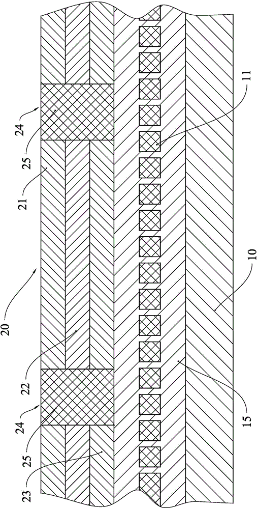
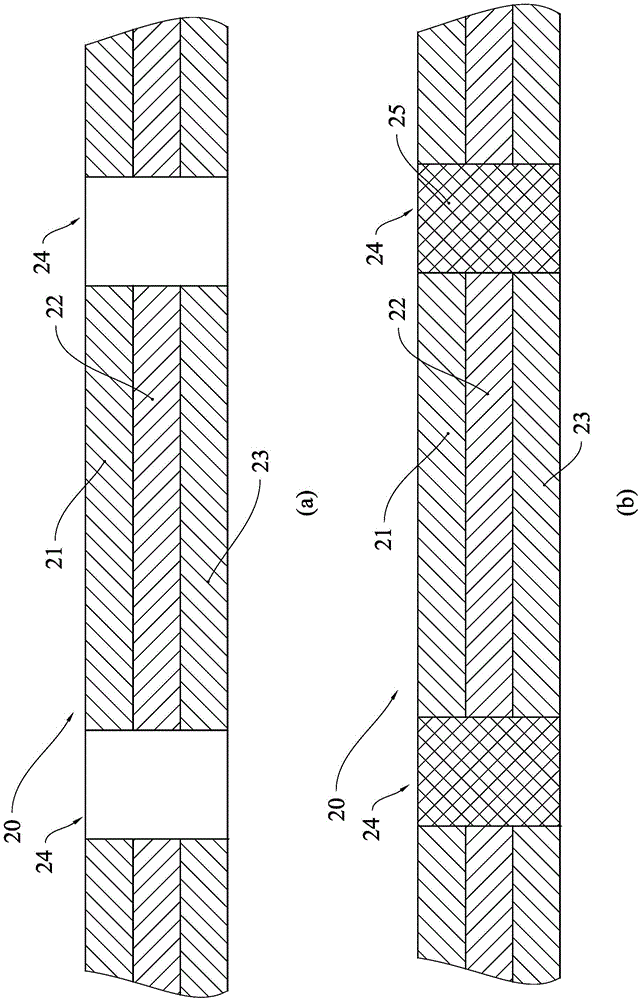
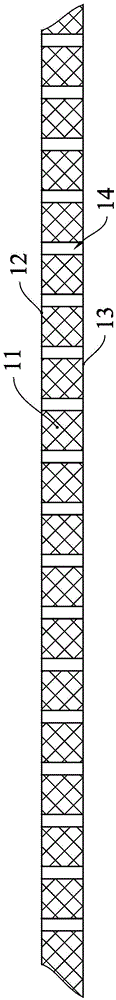
[0033] see figure 1 , the graphite substrate of this embodiment includes a metal layer 20, a graphite sheet 11, an adhesive 13 and a heat dissipation layer 10, wherein the heat dissipation layer 10 is located at the lowermost end of the graphite substrate, the graphite sheet 11 is located above the heat dissipation layer 10, and the metal layer 20 is located at the bottom of the graphite substrate. Above the graphite sheet 11 , the graphite sheet 11 and the heat dissipation layer 10 are connected by an adhesive 15 , and the metal layer 20 and the graphite sheet 11 are also connected by an adhesive 15 . The heat dissipation layer 10 in this embodiment is a substrate made of a material with good heat dissipation capability, such as a copper clad laminate, an aluminum plate, or a ceramic plate. Adhesive glue 15 preferably uses polypropylene (PP material).

[0034] The graphite sheet 11 that present embodiment uses is flexible graphite sheet, preferably, selects the flexible grap...

no. 2 example

[0044] see Figure 4 , the graphite substrate of the present embodiment includes a heat dissipation layer, a heat conduction pad 38 positioned above the heat dissipation layer, a graphite sheet 35 positioned above the heat conduction pad 38, a metal layer 42 positioned above the graphite sheet 35, and a pass between the metal layer 42 and the graphite sheet 35 Adhesive glue 40 connects. Different from the first embodiment, the lower part of the graphite sheet 35 is not connected to the heat dissipation layer by adhesive glue, but is connected by a thermal pad 38 . The heat conduction pad in this embodiment is an elastic pad made of heat conduction rubber or the like.

[0045] The heat dissipation layer of this embodiment is a metal or ceramic radiator 30, the lower end of the radiator 30 has a plurality of protrusions 31 extending downward, and a heat dissipation groove 32 is formed between two adjacent protrusions 31, and the protrusions 31 and heat dissipation The surfaces...


PUM


Abstract

The invention provides a graphite substrate and a manufacture method thereof, an LED module and a manufacture method thereof; the graphite substrate comprises a flexible graphite flake; a metal layer is arranged above the graphite flake; a radiation layer is arranged below the graphite flake; the graphite flake is provided with a plurality of through holes penetrating the top surface and the bottom surface of the graphite flake; the graphite flake is connected with the metal layer through a bonding glue filling the through holes, and the bonding glue directly connects the top surface of the graphite flake with the bottom surface of the metal layer; the graphite flake manufacture method comprises the following steps: arranging the plurality of through holes on the flexible graphite flake, wherein each through hole penetrates the top surface and the bottom surface of the graphite flake; placing a bonding sheet above the graphite flake, placing the metal layer above the bonding sheet, heating the bonding sheet so as to melt the bonding sheet, thus forming the bonding glue filling the through holes; solidifying the bonding glue. The graphite flake directly makes contact with the bonding glue; the heat generated by the LED chip can be fast transferred to the graphite flake, thus realizing fast radiation of the LED module.

Description

technical field [0001] The present invention relates to the field of LED lamps, in particular to a graphite substrate and a method for manufacturing the graphite substrate, and to an LED module made using the graphite substrate and a method for manufacturing the LED module . Background technique [0002] LED lighting devices use light-emitting diodes (LEDs) as light-emitting devices, which have the advantages of energy saving, environmental protection, low power consumption, and long service life, and are widely used in various lighting occasions. The existing LED lighting device has an LED module, the existing LED module has a printed circuit board, and the printed circuit board is provided with an LED chip, and the LED lighting device excites the LED chip to emit light by supplying power to the LED chip during operation. [0003] Because the LED chip generates a lot of heat when it emits light, the LED lighting device needs to be equipped with a heat sink made of metal su...

Claims


Application Information

Patent Timeline
Patent Type & Authority Applications(China)
IPC IPC(8): H05K1/05H05K1/02
CPCH05K1/053H05K1/0203H05K2201/05
Inventor 李保忠罗苑林伟健
Owner RAYBEN TECH ZHUHAI
Why Eureka
Try Eureka