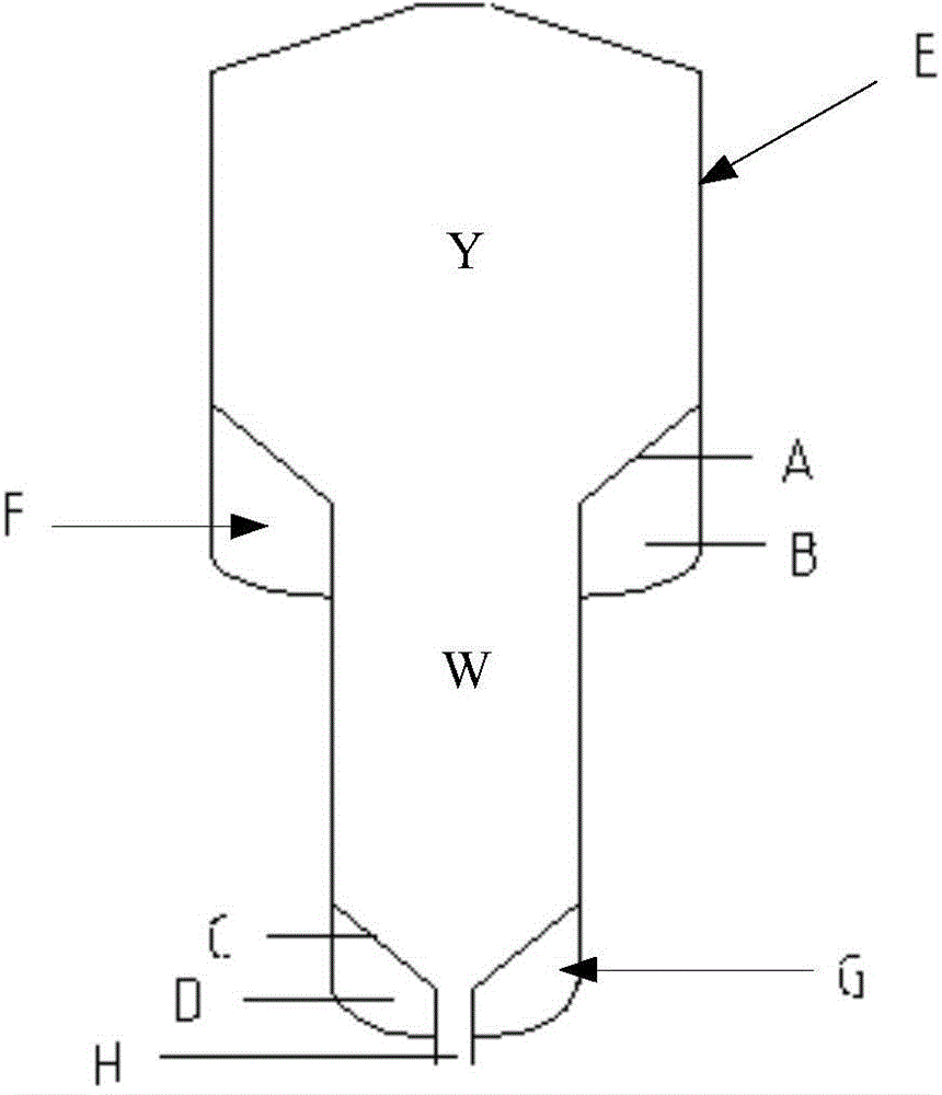
Gasification furnace for cooperatively producing methane and light tar
A light tar and gasifier technology, applied in the direction of granular/powdered fuel gasification, etc., can solve the problems of reducing the conversion rate of carbonaceous raw materials and the degree of pyrolysis, insufficient pyrolysis reaction, and low output of light tar , to increase contact time and contact surface area, improve gasification efficiency, and increase contact time
- Summary
- Abstract
- Description
- Claims
- Application Information
AI Technical Summary
Problems solved by technology
Method used
Image
Examples
Embodiment 1
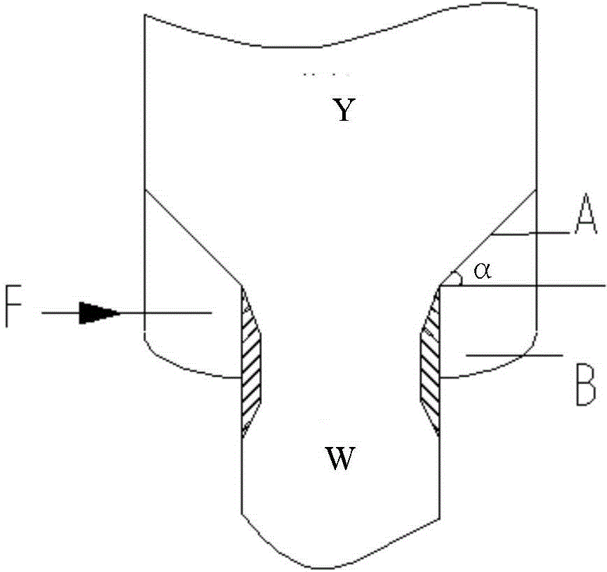
[0033] The distributed plate fluidized bed gasifier of the present invention is adopted, wherein the diameter ratio of the pyrolysis section Y to the gasification section W is 2, and the height ratio of the pyrolysis section Y to the gasification section W is 0.5. use as figure 2 In the design of the pyrolysis section Y distribution plate shown, the angle of the pyrolysis section Y distribution plate is 45°; the opening rate of the pyrolysis section Y distribution plate is 0.4%, and the aperture is 1mm. The catalytic gasification test was carried out using low-quality lignite with a particle size of less than 2 mm. The catalyst was potassium carbonate with a loading capacity of 10 wt%. The pyrolysis fluidization gas adopts the dry gas at the outlet of the gasifier, and the amount of the pyrolysis fluidization gas is 7% of that at the outlet of the gasifier. The operating pressure of the gasifier is 3.0mpa. During the test, the temperature in each area was monitored and the c...
Embodiment 2
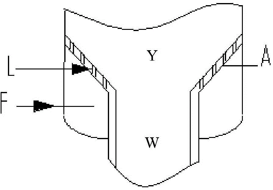
[0041] The distributed plate fluidized bed gasification furnace of the present invention is adopted, wherein the diameter ratio of the pyrolysis section Y to the gasification section W is 2.3, and the height ratio of the pyrolysis section Y to the gasification section W is 0.4. use as image 3 In the design of the pyrolysis distribution plate shown, the angle of the Y distribution plate in the pyrolysis section is 40°; the opening rate of the Y distribution plate in the pyrolysis section is 0.52%, and the aperture is 0.8mm. The catalytic gasification test was carried out using inferior bituminous coal with a particle size of less than 1 mm. The catalyst was potassium carbonate with a loading capacity of 10 wt%. The pyrolysis fluidization gas adopts the dry gas at the outlet of the gasifier, and the amount of the pyrolysis fluidization gas is 8% of the outlet gas of the gasifier. The operating pressure of the gasifier is 3.5mpa. During the test, the temperature in each area wa...
Embodiment 3
[0049] The distributed plate fluidized bed gasification furnace of the present invention is adopted, wherein the diameter ratio of the pyrolysis section Y to the gasification section W is 2.6, and the height ratio of the pyrolysis section Y to the gasification section W is 0.45. use as figure 2 In the design of the pyrolysis distribution plate shown, the angle of the Y distribution plate in the pyrolysis section is 55°; the opening rate of the Y distribution plate in the pyrolysis section is 0.4%, and the aperture is 1.5mm. The catalytic gasification test was carried out using bituminous coal with a particle size of less than 1mm. The catalyst was potassium carbonate with a loading capacity of 10wt%. The pyrolysis fluidization gas adopts the dry gas at the outlet of the gasifier, and the amount of the pyrolysis fluidization gas is 8% of the outlet gas of the gasifier. The pressure is 3.0mpa. During the test, the temperature of each area is monitored and the composition of th...
PUM
| Property | Measurement | Unit |
|---|---|---|
| pore size | aaaaa | aaaaa |
| pore size | aaaaa | aaaaa |
| pore size | aaaaa | aaaaa |
Abstract
Description
Claims
Application Information
 - R&D
- Intellectual Property
- Life Sciences
- Materials
- Tech Scout
- Unparalleled Data Quality
- Higher Quality Content
- 60% Fewer Hallucinations
Browse by: Latest US Patents, China's latest patents, Technical Efficacy Thesaurus, Application Domain, Technology Topic, Popular Technical Reports.
© 2025 PatSnap. All rights reserved.Legal|Privacy policy|Modern Slavery Act Transparency Statement|Sitemap|About US| Contact US: help@patsnap.com


