Supercharge Your Innovation With Domain-Expert AI Agents!

Anti-scaling evaporation cooling equipment for coal gas dry dedusting of converter

A dry dust removal and evaporative cooling technology, applied in the manufacture of converters, etc., can solve the problems of substandard dust emission, easy ash clogging, pollution of the environment, etc., to reduce equipment failure rate, ensure normal production, and solve the effect of site restrictions

Inactive Publication Date: 2015-09-09
WISDRI ENG & RES INC LTD
View PDF5 Cites 1 Cited by
  • Summary
  • Abstract
  • Description
  • Claims
  • Application Information

AI Technical Summary

Problems solved by technology

[0003] The main problems of the existing converter gas dry dedusting equipment: First, the double-flow spray gun is installed at the end of the vaporization cooling flue, and it is necessary to open holes in the vaporization cooling flue, especially in the transformation project of wet to dry dedusting, the vaporizer must be replaced. The end of the cooling flue increases equipment investment and installation difficulty; second, the inner wall of the evaporative cooling tower is prone to fouling, and the built-in double-chain conveyor has a high failure rate, which is easy to get stuck, which in turn affects the normal production of the converter; third, the height of the evaporative cooling tower is affected. Due to the restriction of the high-rise framework, the banana bend of the renovation project often interferes with the slag stopper at the back of the furnace, which affects the sampling of molten steel; Fourth, in the initial stage of converter smelting, the second shot and the later stage of smelting, the chimney emits smoke, and the dust emission is not up to standard, polluting the environment

Method used


Image

  • Anti-scaling evaporation cooling equipment for coal gas dry dedusting of converter

Examples


Embodiment Construction

[0019] In order to have a clearer understanding of the technical features, purposes and effects of the present invention, the specific implementation manners of the present invention will now be described in detail with reference to the accompanying drawings.

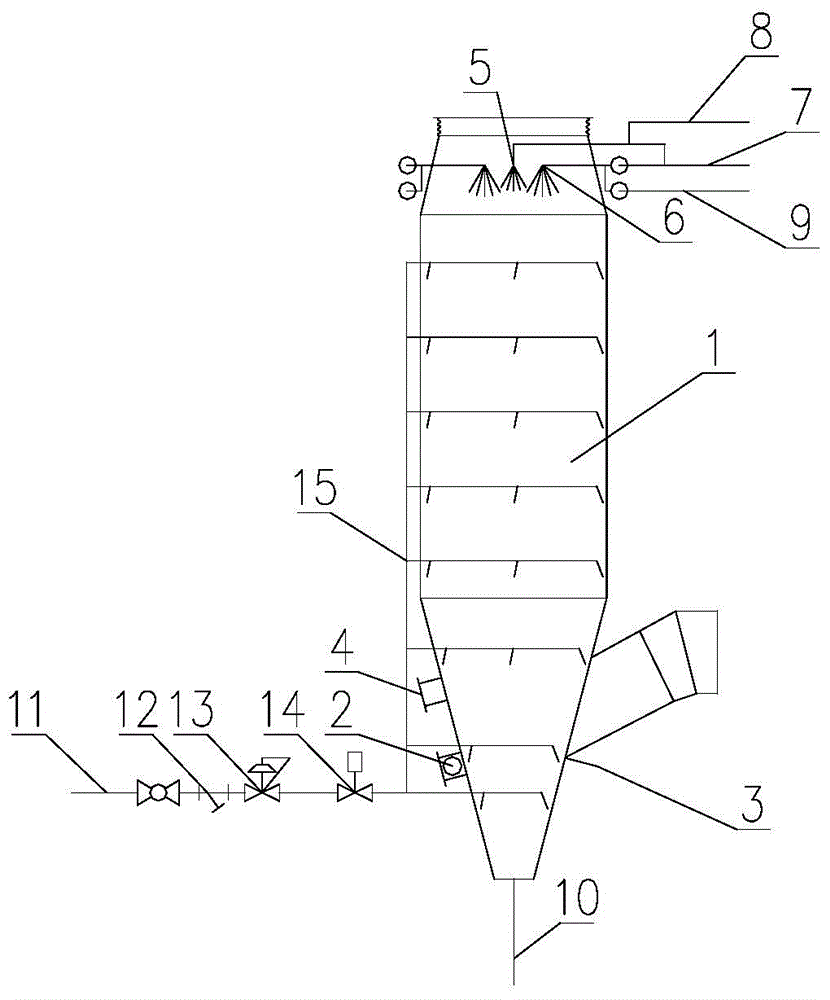
[0020] like figure 1 As shown, the converter gas dry dust removal and anti-scaling evaporative cooling equipment of the present invention includes an anti-scaling evaporative cooler 1, a rapping device 2, a dual-medium conditioning spray gun 5, a dual-medium cooling spray gun 6 and a blowing and cleaning device 15 ;

[0021] The anti-scaling evaporative cooler 1 entrance is equipped with a high-temperature resistant non-metallic compensator for compensating for thermal expansion and contraction of the equipment; the outlet of the lower cone bucket is connected to the ash discharge main pipe 10, and the coarse ash collected by the lower cone bucket falls into the coarse ash under the action of gravity warehouse; the ant...


PUM


Abstract

The invention relates to an anti-scaling evaporation cooling equipment for coal gas dry dedusting of a converter. The anti-scaling evaporation cooling equipment comprises an anti-scaling evaporation cooler (1), a rapping device (2), a double-medium tempering spray gun (5), a double-medium cooling spray gun (6) and a spray-blowing deashing device (15). A high-temperature-resistance nonmetal compensator is arranged at an inlet of the anti-scaling evaporation cooler (1), an outlet of a lower cone funnel is connected with a deashing manifold (10), and the spray-blowing deashing device (15) is arranged around the anti-scaling evaporation cooler (1). By the anti-scaling evaporation cooling equipment, the problem of hole forming on a vaporization cooling flue of a double-flow spray gun is solved, the problem that the inner wall of an evaporation cooling tower is prone to scaling is solved, the problem that height of the evaporation cooling tower is limited by sites during dry dedusting modification is solved, and the problem that dust discharging of a diffusing chimney at the early stage of smelting of the converter, at the stage of secondary gun lowering and at the later stage of smelting does not reach the standards is solved. The anti-scaling evaporation cooling equipment is especially suitable for projects of primary smoke wet dedusting to dry dedusting of the converter and is wide in application prospect.

Description

technical field [0001] The invention relates to the field of environmental protection equipment, more specifically, to a converter gas dry dust removal anti-fouling evaporative cooling equipment. Background technique [0002] With the continuous strengthening of environmental protection awareness, most of the newly built and rebuilt converters adopt dry dust removal system. The conventional layout of the dry dedusting equipment in the converter main workshop is as follows: the double-flow spray gun is installed at the end of the evaporative cooling flue, spraying water mist into the evaporative cooling tower to cool down and reduce dust, and to condition the raw gas; the coarse ash collected by the banana bend passes through the The built-in double chain conveyor sends it to the coarse ash bin, which is transported by the ash truck. [0003] The main problems of the existing converter gas dry dedusting equipment: First, the double-flow spray gun is installed at the end of t...

Claims


Application Information

Patent Timeline
IPC IPC(8): C21C5/40
Inventor 葛雷王勇纲王亮纪世昌
Owner WISDRI ENG & RES INC LTD
Features
  • R&D
  • Intellectual Property
  • Life Sciences
  • Materials
  • Tech Scout
  • Unparalleled Data Quality
  • Higher Quality Content
  • 60% Fewer Hallucinations
Learn More