Method of metalizing reverse side of single pipe core

A technology of backside and metallization of die, applied in metal material coating process, ion implantation plating, coating and other directions, can solve the problem of difficult implementation of die, and achieve the effect of saving time, good use effect and simple operation

Active Publication Date: 2015-09-09
JINZHOU 777 MICROELECTRONICS
View PDF5 Cites 4 Cited by
  • Summary
  • Abstract
  • Description
  • Claims
  • Application Information

AI Technical Summary

Problems solved by technology

However, the basic requirement of eutectic sintering is that there is a metallized layer on the back of the die. At present, most of the dies imported from abroad do not have a metallized layer on the back of the die, and they are all single small dies that cannot be clamped to the metal. On the fixture of the metallization equipment, this makes it difficult to implement the backside metallization of a single die

Method used


Image

  • Method of metalizing reverse side of single pipe core
  • Method of metalizing reverse side of single pipe core

Examples


Embodiment 1

[0024] Metallize the back of the die with a specification (length×width×thickness) of 4.65mm×3.95mm×0.45mm. The specific steps are as follows:

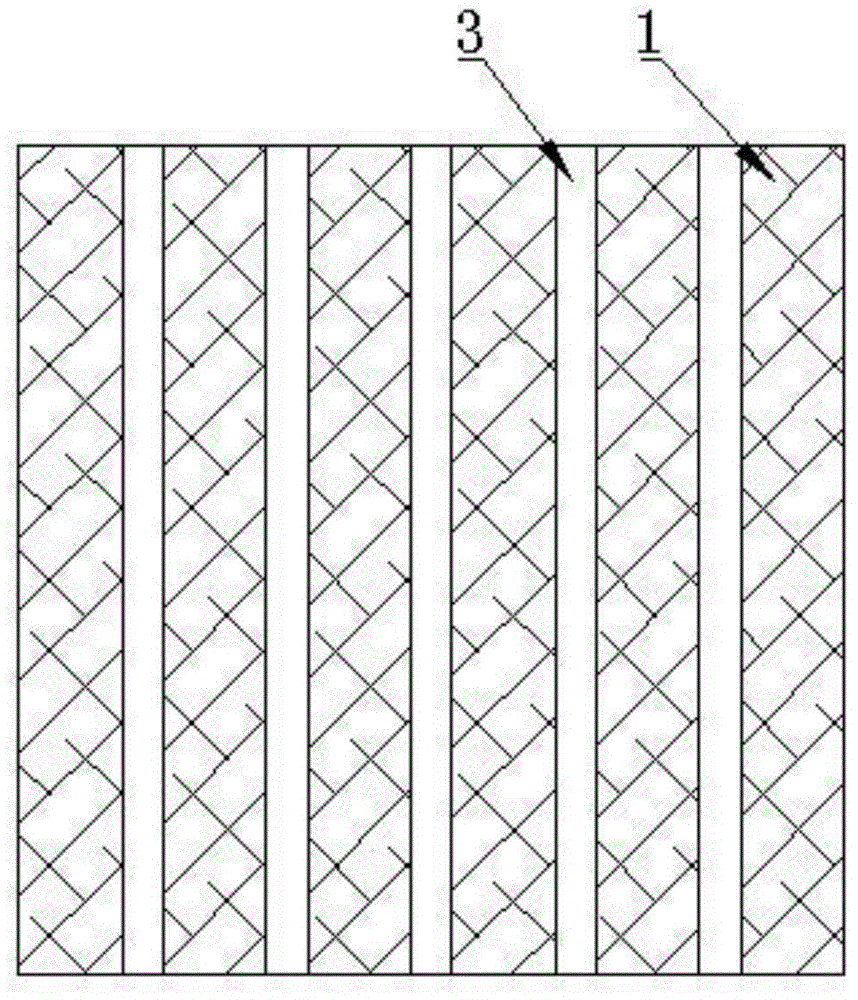
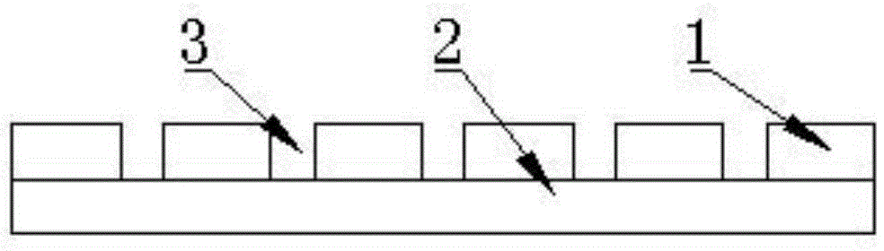
[0025] (1), the glass-ceramics substrate that the thickness is 0.5mm is divided into the glass-ceramics spacer bar that width is 6mm, get 6 glass-ceramic spacer bars and be bonded on the film crystallite that the thickness of substrate is 0.5mm On the glass substrate, the two adjacent glass-ceramic spacers form a die placement groove with a width of 3.97 mm, and are made into a die placement mold with five die placement grooves, as shown in the figure;

[0026] (2), take 5 individual tube cores and place them respectively in the tube core placement grooves of the tube core placement mold with the back facing up, and send them into the sputtering chamber of the magnetron sputtering table, and the purity of the feed is 99.99% % argon as the reaction gas, the gas flow rate is 12sccm, and the vacuum degree of the control sputtering chambe...

Embodiment 2

[0032] Metallize the back of the die with a specification (length×width×thickness) of 4mm×3.15mm×0.42mm. The specific steps are as follows:

[0033] (1), making die placement mold

[0034] A glass-ceramic substrate with a thickness of 0.5 mm is divided into glass-ceramic spacers with a width of 5.5 mm, and 6 glass-ceramic spacers are bonded on the thin-film glass-ceramic substrate as the substrate. Two glass-ceramic spacers form a die placement groove with a width of 3.175mm, and make a die placement mold with five die placement grooves, as shown in the figure;

[0035] (2), take 5 individual tube cores and place them respectively in the tube core placement grooves of the tube core placement mold with the back facing up, and send them into the sputtering chamber of the magnetron sputtering table, and the purity of the feed is 99.99% % argon as the reaction gas, the gas flow rate is 13sccm, and the vacuum degree of the control sputtering chamber is 5.5×10 -5 Pa;

[0036] (3)...

Embodiment 3

[0041] Metallize the back of the die with a specification (length×width×thickness) of 2.5mm×1.5mm×0.44mm. The specific steps are as follows:

[0042] (1), making die placement mold

[0043] A glass-ceramic substrate with a thickness of 0.5 mm is divided into glass-ceramic spacers with a width of 5 mm, and 6 glass-ceramic spacers are bonded on the thin-film glass-ceramic substrate as the substrate. A glass-ceramic spacer forms a die placement groove with a width of 1.53mm, and is made into a die placement mold with five die placement grooves, as shown in the figure;

[0044] (2), take 5 individual tube cores and place them respectively in the tube core placement grooves of the tube core placement mold with the back facing up, and send them into the sputtering chamber of the magnetron sputtering table, and the purity of the feed is 99.99% % argon as the reaction gas, the gas flow rate is 14sccm, and the vacuum degree of the control sputtering chamber is 5×10 -5 Pa;

[0045] (...


PUM

PropertyMeasurementUnit
thicknessaaaaaaaaaa
thicknessaaaaaaaaaa
thicknessaaaaaaaaaa

Abstract

The invention discloses a method of metalizing the reverse side of a single pipe core. A glass ceramics substrate is divided into glass ceramics partition strips, and the glass ceramics partition strips are adhered to a film glass ceramics substrate as a substrate, so that a pipe core holding groove is formed between two adjacent glass ceramics partitions strips; the reverse side of the single pipe core is upwards placed in the pipe core holding groove of a pipe core holding die and the pipe core holding die is sent into a sputtering chamber of a magnetron sputtering platform; argon is introduced in the sputtering chamber to be used as a reactant gas; the pipe core is firstly subjected to reactive sputtering and then is subjected to magnetron sputtering; an adherency barrier layer is deposited on the reverse side of the pipe core by using a NiCr alloy target; a welding layer is deposited on the reverse side of the pipe core by using an Au target material with the purify of 99.99%; and after sputtering is completed, the die is taken out, and the pipe core subjected to sputtering treatment is placed in a chip box. The invention has the advantages that the technology is reasonable; the operation is simple; the reverse side metalizing treatment can be carried out on the single pipe core with a relatively small size; and the method is suitable for industrial production.

Description

technical field [0001] The invention relates to a method for metallizing the back of a tube core, in particular to a method for metallizing the back of a single small tube core. Background technique [0002] In recent years, with the rapid development of integrated circuit technology, the guarantee and improvement of integrated circuit reliability are facing great challenges. The requirements for the welding process of chips used in the manufacture of integrated circuits in integrated circuits are getting higher and higher. Due to the thermal properties of eutectic sintering , Electrical properties and mechanical properties are much better than conductive adhesive bonding, so it is required to use eutectic sintering instead of using traditional organic adhesives in the way of interconnection between chips and sockets, chips and substrates. However, the basic requirement of eutectic sintering is that there is a metallized layer on the back of the die. At present, most of the ...

Claims


Application Information

Patent Timeline
Patent Type & Authority Applications(China)
IPC IPC(8): C23C14/35C23C14/02C23C14/14
Inventor 马建军程梦莲白艳张帆
Owner JINZHOU 777 MICROELECTRONICS
Why Eureka
Try Eureka