
Device and method for testing impact performance of spot welded joints of thin metal plates

A technology for impact performance of metal sheets, applied in the field of impact performance testing devices for spot welded joints of metal sheets, can solve the problems affecting the accuracy of impact force measurement results, affecting the transmission of impact energy, and the complex structure of force measurement circuits, etc., to achieve inertia force Small influence, improved measurement accuracy, and simple structure

Active Publication Date: 2017-07-07
NORTHEASTERN UNIV LIAONING
View PDF2 Cites 0 Cited by
  • Summary
  • Abstract
  • Description
  • Claims
  • Application Information

AI Technical Summary

Problems solved by technology

This kind of testing machine does not directly measure the impact force, but uses the support reaction force measured by four force-measuring units to obtain the impact force through conversion. Due to the complex structure of the force-measuring circuit and many intermediate conversion links, it affects the accuracy of the impact force measurement results.
In addition, the double pendulum scheme is adopted, the structure of the testing machine is complex, and there are sample size errors and installation errors, which may easily cause the impact contact between the active pendulum and the driven pendulum to occur at the upper or lower part of the driven pendulum, affecting the impact. The transfer of energy also affects the accuracy of the measurement
Furthermore, special forming equipment is required to make "Z" shaped samples

Method used


Image

  • Device and method for testing impact performance of spot welded joints of thin metal plates
  • Device and method for testing impact performance of spot welded joints of thin metal plates
  • Device and method for testing impact performance of spot welded joints of thin metal plates

Examples


Embodiment Construction

[0038] The present invention will be further described below in conjunction with drawings and embodiments.

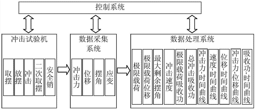
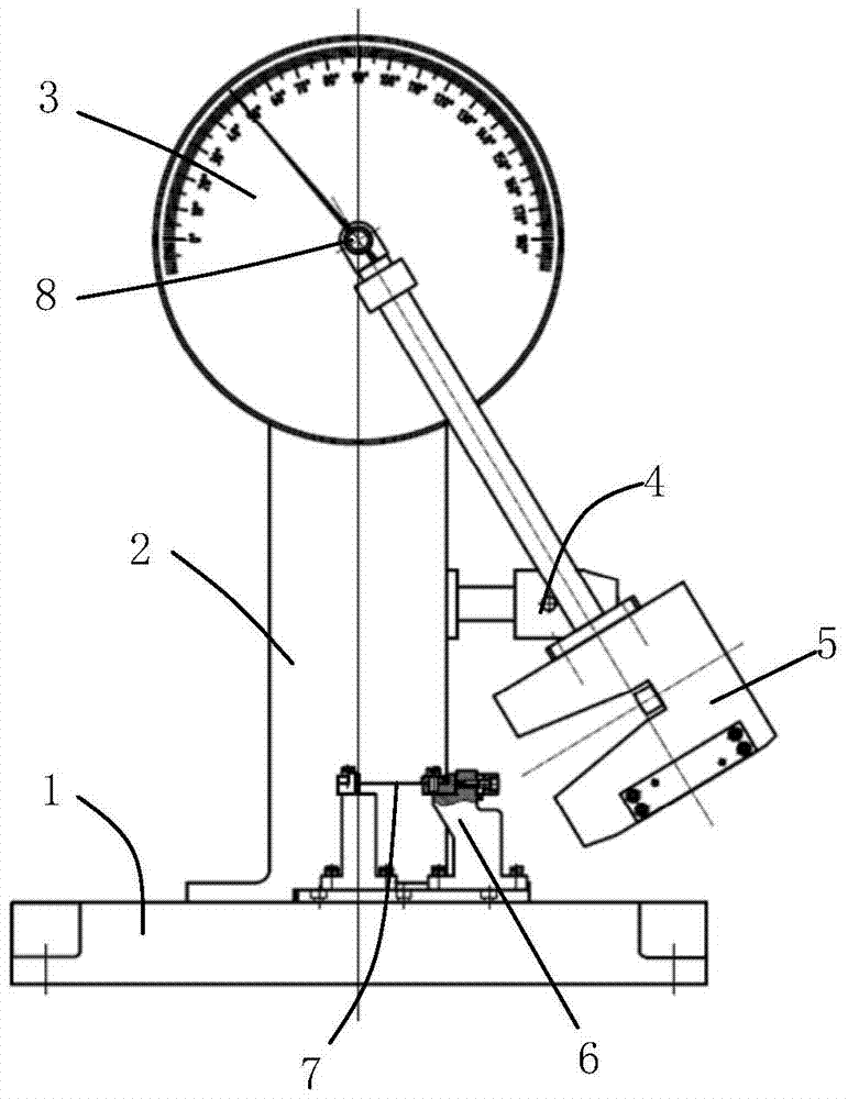
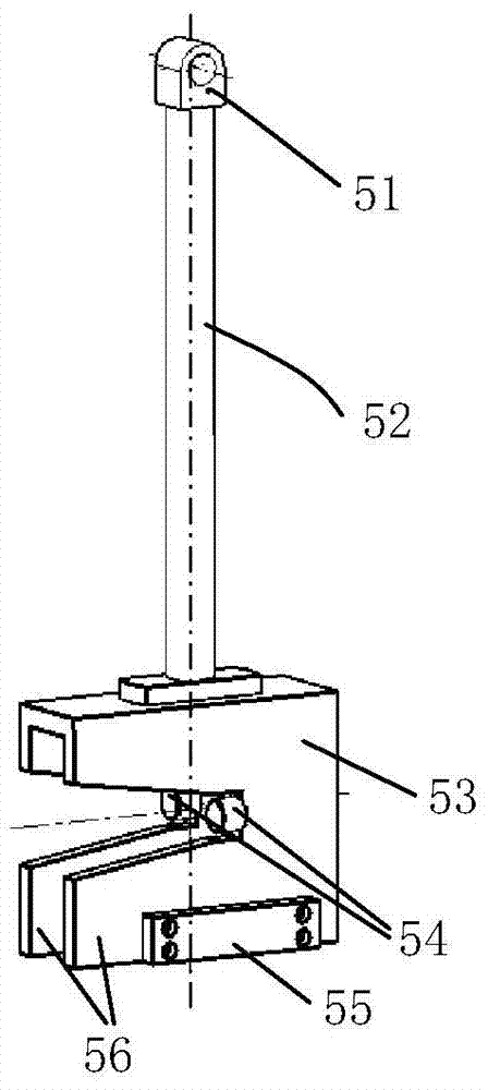
[0039] combine figure 1 with figure 2 , The metal sheet spot welding joint impact performance testing device of the present invention includes an impact testing machine, an impact fixture 6, a control system, a data acquisition system and a data processing system. The impact testing machine is composed of a base 1, a column 2, a pendulum shaft 8, a pendulum 5, a pendulum angle dial 3, a pendulum taking mechanism and a safety pin 4. The column 2 is fixedly installed on the base 1, the swing angle dial 3 is installed on the upper end of the column 2, the pendulum taking mechanism (not shown) composed of a servo motor and a clutch is installed on the upper part of the column, and the safety pin 4 for locking the pendulum Installed in the middle of the column. Such as image 3 , Figure 4 with Figure 5 As shown, the pendulum 5 is composed of a pendulum 52 and a pend...


PUM


Abstract

A metal sheet spot welded joint impact performance test device consisting of an impact testing machine, impact fixture, control system, data acquisition and processing system. When using it to test the impact performance of a spot welded joint, the two ends of the sample are respectively fixed on the impact fixture On the movable jaw and the fixed jaw, the pendulum is used to apply an impact load to the spot welding joint to break the spot welding joint, and the data acquisition system collects the points measured by the force sensor between the fixed jaw and the fixed jaw support. The impact force on the welding head, the displacement of the free end of the sample and the angle of the pendulum measured by the laser displacement sensor on the side of the movable jaw, the data processing system gives the ultimate load, ultimate load displacement, and ultimate load impact that characterize the impact performance of the spot welding joint Absorbed energy, total impact absorbed energy, impact force-time curve, displacement-time curve, velocity-time curve, impact force-displacement curve, impact absorbed energy-time curve, used to evaluate and study the impact performance of spot welding joints.

Description

technical field [0001] The invention relates to welding technology, in particular to a device and method for testing the impact performance of spot welded joints of thin metal plates. Background technique [0002] The spot welding connection process of metal sheets is widely used in the field of automobile manufacturing. The connection strength of spot welding joints directly affects the safety and service life of the automobile body, and is an important indicator for evaluating the safety performance of automobiles. In the past, the static method was mainly used to test the strength of spot welded joints, that is, to apply quasi-static tension to various spot welded samples such as tensile shear, cross tensile or tensile peeling, to obtain the maximum load when the spot welded joint is damaged Capability (ultimate load), deformation (displacement) and absorbed energy of the sample at the moment corresponding to the ultimate load, failure mode of solder joint (welding nugget...

Claims


Application Information

Patent Timeline
Patent Type & Authority Patents(China)
IPC IPC(8): G01M7/08
Inventor 花福安李建平牛文勇孙涛宫传慧王国栋
Owner NORTHEASTERN UNIV LIAONING
Learn More