Flow battery negative electrolyte solution sealing system and flow battery system

A negative electrode electrolyte and flow battery technology, applied in fuel cells, regenerative fuel cells, sealing/supporting devices, etc., can solve the problems of carbon felt losing its electrical conductivity and catalytic function, unable to characterize, and sticking to its surface, etc., to achieve Good operation safety and stability, good fluidity and air tightness, and the effect of reducing the capacity decay speed

Active Publication Date: 2015-09-09
DALIAN RONGKE POWER
View PDF5 Cites 13 Cited by
  • Summary
  • Abstract
  • Description
  • Claims
  • Application Information

AI Technical Summary

Problems solved by technology

[0004] In recent years, scientific research institutes have carried out a lot of research on the sealing performance of negative electrode storage tanks. However, due to the material characteristics of the solution storage tanks, it has been impossible to achieve absolute sealing of the electrolyte storage tanks for many years. In 1994, European patent EP0729648B1 once proposed To the sealing method of laying a layer of mineral oil with a thickness of about 50-300mm on the surface of the negative electrode solution, the prospect of using grease to seal the electrolyte is expected
Tests have proved that due to the good fluidity and air tightness of liquid grease, the grease seal has achieved a good effect of isolating the air from the negative electrode solution, but the static test cannot characterize the charging and discharging operation of the battery system, and due to the characteristics of the grease itself- Insulation, adhesion and fluidity, in addition to the storage tank wall, during the circulation process of the flow battery system, grease should be strictly prevented from entering the battery stack, otherwise the grease will contact the carbon felt electrode and adhere to its surface, making the carbon felt Losing the conductive and catalytic functions will cause irreversible damage to the flow battery, such as a sharp drop in system capacity and efficiency

Method used


Image

  • Flow battery negative electrolyte solution sealing system and flow battery system
  • Flow battery negative electrolyte solution sealing system and flow battery system
  • Flow battery negative electrolyte solution sealing system and flow battery system

Examples


Embodiment 1

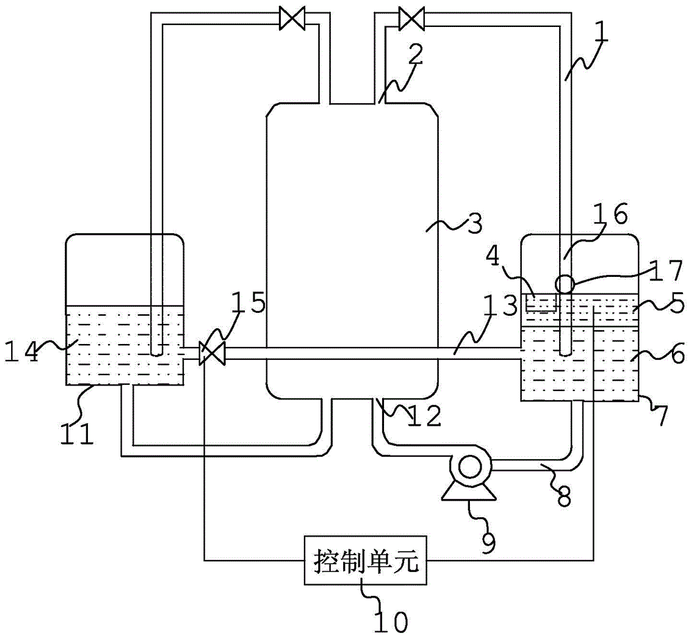
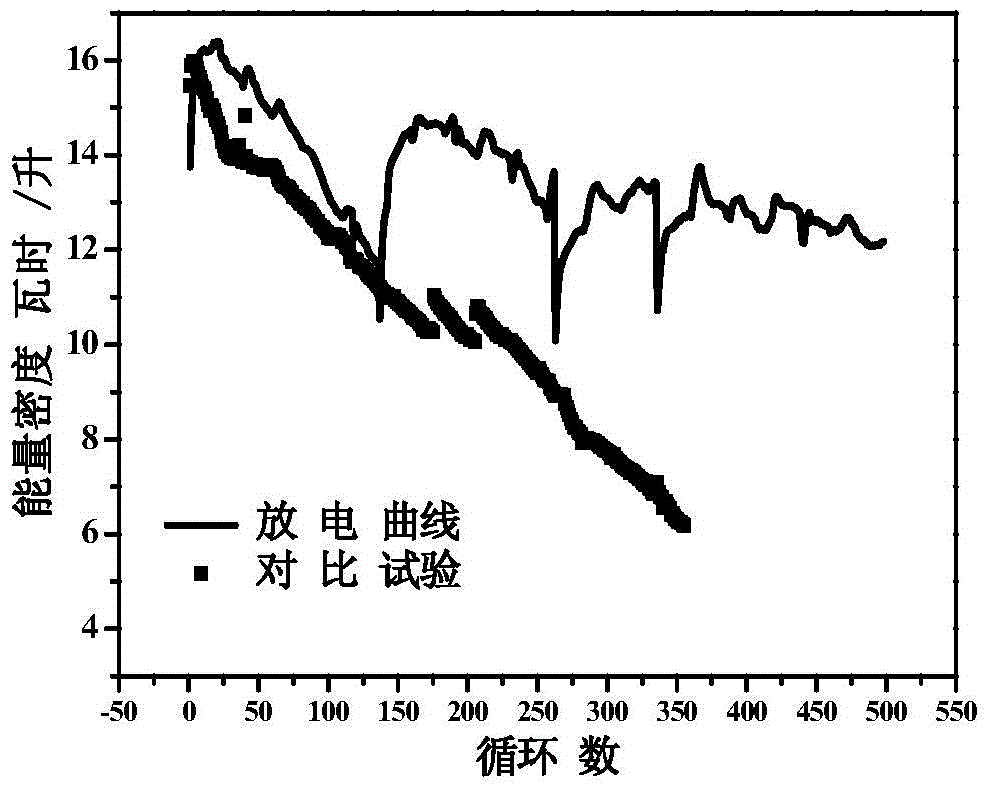
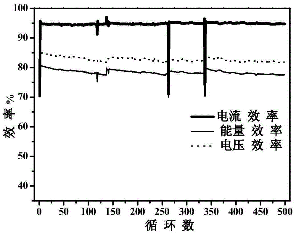
[0038] Table 1 is the test parameter table of the organic matter sealing test 1, figure 2 is the curve graph of the energy density in the organic sealing experiment 1 with the number of charge and discharge cycles, image 3 is the change curve of the efficiency in the organic matter sealing experiment 1 with the number of charge and discharge cycles, as shown in Table 1, figure 2 with image 3 As shown, the premise is to adopt the seal of the organic matter layer. The organic matter is esters, specifically vegetable oil (the main component is triglyceride), and the negative electrode electrolyte outlet of the stack is connected to the negative electrode storage tank through the first pipeline to ensure that the second The outlet of the negative electrode electrolyte of the first pipeline is always located below the liquid level of the negative electrode electrolyte, which can realize the long-term operation of the sealed system without affecting the flow battery. The flow b...

Embodiment 2

[0042] Table 2 is the test parameter list of the organic sealing experiment 2, Figure 4 is the graph of the change of energy density with the number of charge and discharge cycles in the organic matter sealing experiment 2, Figure 5 It is a curve diagram of the efficiency in the organic matter sealing experiment 2 with the number of charge and discharge cycles. Table 3 is the attenuation and efficiency data table of the organic matter sealing experiment 2, such as table 2, Figure 4 , Figure 5 As shown in Table 3, the premise is to adopt the seal of the organic matter layer. The organic matter adopts esters, specifically mineral oil. The negative electrode electrolyte outlet and the negative electrode storage tank are connected to the negative electrode storage tank and the negative electrode electrolyte inlet of the stack through the second pipeline, and the negative electrode storage tank and the positive electrode storage tank are connected through the communication pip...

Embodiment 3

[0049] Table 4 is the test parameter table of organic matter sealing experiment 3, and table 5 is the test result data table of organic matter sealing experiment 3, in order to investigate the discharge capacity retention of the flow battery system with the negative storage tank sealing system during long-term storage after full charge , as shown in Table 4 and Table 5, the organic matter is a mixture of esters and alkanes, specifically a mixture of soybean oil and dodecane. The test uses a 2kW flow battery system. After the system is charged, at this time in the negative electrode electrolyte The divalent vanadium V2+ has reached a certain concentration, put the system discharge program on hold, stop the circulation pump, start the circulation pump and discharge program again after standing for a period of time, and investigate the changes of system parameters.

[0050] Table 4. Table of test parameters for organic matter sealing experiment 3.

[0051] project

v...


PUM

PropertyMeasurementUnit
densityaaaaaaaaaa
thicknessaaaaaaaaaa
densityaaaaaaaaaa

Abstract

The invention discloses a flow battery negative electrolyte solution sealing system and a flow battery system. The flow battery negative electrolyte solution sealing system comprises: an organic matter layer disposed on the negative electrolyte solution in a negative storage tank; a first pipeline connected to the negative electrolyte solution outlet of an electric pile and the negative storage tank, with one end of the first pipeline connected to the negative electrolyte solution outlet of the electric pile and the other end placed in the negative electrolyte solution; and a second pipeline connected to the negative storage tank and the negative electrolyte solution inlet of the electric pile. According to the invention, the organic matter layer is disposed on the negative electrolyte solution in the negative storage tank, and liquid state organic molecules have good fluidity and air tightness, thus ensuring good air isolation effect of the negative electrolyte solution to air, and the negative storage tank and a positive storage tank are connected by pipelines, thus ensuring the negative electrolyte solution in a safe liquid level state. Also compared with common flow battery systems, the capacity fading speed is reduced, and the flow battery system provided by the invention has good operation safety and stability.

Description

technical field [0001] The invention relates to the field of liquid flow batteries, in particular to a liquid flow battery negative electrode electrolyte sealing system and a liquid flow battery system. Background technique [0002] The increasing demand for traditional energy in the development of modern economy and society has made the problem of insufficient supply of traditional energy increasingly prominent, and people have to look for renewable energy such as wind energy and solar energy. In recent years, new energy represented by wind energy and solar energy has occupied a place in energy supply. With the increase of demand, the proportion of new energy is still increasing, but the defect of intermittent power generation caused by the influence of weather still exists. become a bottleneck hindering its development. Due to its huge energy storage advantages, flow batteries have received more and more attention, and there are continuous reports of MW-level demonstratio...

Claims


Application Information

Patent Timeline
Patent Type & Authority Applications(China)
IPC IPC(8): H01M8/02H01M8/18
CPCH01M8/0271H01M8/0284H01M8/18Y02E60/50
Inventor 高新亮张华民许晓波王晓丽刘若男李颖林则青邹毅杨振坤
Owner DALIAN RONGKE POWER
Why Eureka
Try Eureka