Ridge waveguide bias slot coupling micro-strip oscillator dual polarized antenna

A dual-polarized antenna and microstrip vibrator technology is applied in leaky waveguide antennas, antenna unit combinations with different polarization directions, and antenna grounding switch structure connection, etc. Effect

Active Publication Date: 2015-09-09
ANHUI SUN CREATE ELECTRONICS
View PDF4 Cites 18 Cited by
  • Summary
  • Abstract
  • Description
  • Claims
  • Application Information

AI Technical Summary

Problems solved by technology

Foreign Raysat and KVH respectively have a dual-polarized array antenna for Ku-band satellite TV reception, both adopt the microstrip patch type, which is an early product, and the production cost is an order of magnitude higher

Method used


Image

  • Ridge waveguide bias slot coupling micro-strip oscillator dual polarized antenna
  • Ridge waveguide bias slot coupling micro-strip oscillator dual polarized antenna
  • Ridge waveguide bias slot coupling micro-strip oscillator dual polarized antenna

Examples


Embodiment 1

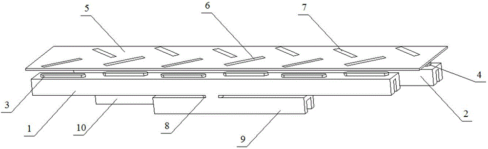
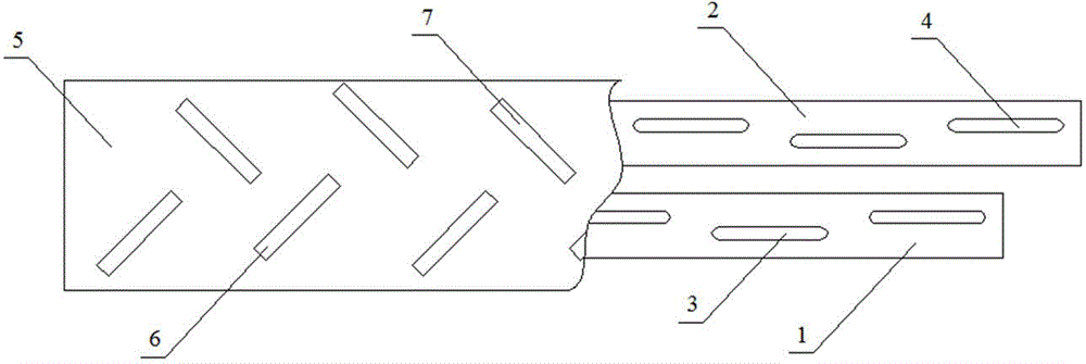
[0038] see figure 1 and figure 2 , a ridge waveguide offset slot coupled microstrip dipole dual-polarized antenna, including two ridge waveguide offset slot resonant array antenna units arranged side by side; see image 3 and Figure 4, the first radiation waveguide 1 and the first feeding waveguide 9 are connected to form a unit through the I-shaped coupling slot 8, and six biased first radiation slots 3 are evenly distributed on the wide side of the first radiation waveguide 1; The radiation waveguide 2 and the second feeding waveguide 10 are connected by an I-shaped coupling slot 8 to form another unit, and six offset second radiation slots 4 are uniformly arranged on the wide side of the second radiation waveguide 2 . The first radiation slot 3 and the second radiation slot 4 have the same width, length, and distance away from the center line of the radiation waveguide. The radiation intensity of the offset radiation slot is related to the offset amount, and the unbiase...

Embodiment 2

[0046] A 6×2 unit dual-polarization antenna planar array composed of two ridge waveguide offset slot-coupled microstrip dipole dual-polarization antenna units arranged side by side.

[0047] see Figure 5 and Figure 6 , with the ridge waveguide offset slot coupled microstrip dipole dual-polarized antenna in embodiment 1 as the antenna element, two antenna elements are arranged side by side to form a ridge waveguide offset slot coupled microstrip dipole dual-polarized antenna array; adjacent antennas The feeding end of the first feeding waveguide 9 of the unit is connected to the first outlet waveguide 13 through the feeding network, and the feeding end of the second feeding waveguide 10 of the adjacent antenna unit is connected to the second outlet waveguide 14 through the feeding network .

[0048] Depend on Figure 6 It can be seen that the feed network includes two T-shaped power dividers 11 and two ridge waveguides; the feed waveguides of the same polarization are comb...

Embodiment 3

[0051] A 6×8 element dual-polarization antenna planar array composed of eight ridge waveguide offset slot-coupled microstrip dipole dual-polarization antenna elements arranged side by side.

[0052] see Figure 7 , Figure 8 and Figure 9 , which consists of eight antenna elements arranged side by side to form a ridge waveguide offset slot coupled microstrip dipole dual-polarized antenna array; Figure 8 and Figure 9 It can be seen that the feed network has three layers, and two adjacent ridge waveguides are connected by power dividing coupling slots 12 to form a two-layer feed network; Transition to another layer of ridge waveguides, and finally the three-layer feed network with the same polarization has only one synthesis port.

[0053] The array antenna feeding network includes four T-shaped power dividers 11 and two layers of ridge waveguides; the feed waveguides of the same polarization are synthesized together by the T-shaped power dividers 11, and the output termin...


PUM


Abstract

The invention relates to a ridge waveguide bias slot coupling micro-strip oscillator dual polarized antenna. The antenna comprises two parallel arranged ridge waveguide bias slot coupling micro-strip oscillator dual polarized antenna units, more than two positive metal pasters and more than two negative metal pasters, wherein the positive metal pasters and the negative metal pasters are uniformly arranged on the outer side face of a micro-strip plate. Centers of the positive metal pasters correspond to more than two radiation seams on a first radiating waveguide. Centers of the negative metal pasters correspond to more than two radiation seams on a second radiation waveguide. The positive metal pasters and the negative metal pasters are coupling micro-strip oscillators, thereby achieving dual polarization. According to the invention, a ridge waveguide structure is adopted, thereby achieving dual polarization and low profiles; I-shaped coupling seams are used for direct coupling feeding, thereby achieving integrated design of antennas and feeder lines; and the antennas can freely from large plane arrays as units.

Description

technical field [0001] The invention belongs to the technical field of panel antennas, and in particular relates to a ridge waveguide offset slot coupled microstrip dipole dual-polarization antenna. Background technique [0002] Array antennas are widely used in mobile communication fields such as airborne, ship-borne, and vehicle-mounted. Compared with reflector antennas, array antennas can conveniently achieve a low profile and have higher efficiency. Today, with the further development of the manufacturing process, the price of the array antenna has been greatly reduced, but it is still higher than that of the reflector antenna, especially the price of the dual-polarized panel antenna is higher. At present, the existing solutions are similar to the horn array antenna in the field of communication in motion, full waveguide structure, wide bandwidth, high efficiency, dual polarization oblique beam waveguide slot array antenna, using two different structures of slot travelin...

Claims


Application Information

Patent Timeline
Patent Type & Authority Applications(China)
IPC IPC(8): H01Q1/38H01Q1/50H01Q13/22H01Q21/24
Inventor 胡卫东金秀梅
Owner ANHUI SUN CREATE ELECTRONICS
Why Eureka
Try Eureka