Fuel combustion system with a perforated reaction holder

A stabilizer and reaction technology, applied to gas fuel burners, burning with multiple fuels, burners, etc., can solve problems such as long residence time, uneven heating of steam pipes, etc.

Active Publication Date: 2015-09-09
美一蓝技术公司
View PDF5 Cites 6 Cited by
  • Summary
  • Abstract
  • Description
  • Claims
  • Application Information

AI Technical Summary

Problems solved by technology

This unpredictability, coupled with the high peak temperatures encountered in a diffusion flame, especially at the stoichiometric interface (visible surface), can lead to operational problems, such as reaction tube scorching and / or vapor tube inhomogeneity heating
Furthermore, the length of conventional flames results in relatively long residence times during which the combustion air (including molecular nitrogen) is subjected to high temperatures

Method used


Image

  • Fuel combustion system with a perforated reaction holder
  • Fuel combustion system with a perforated reaction holder
  • Fuel combustion system with a perforated reaction holder

Examples


example

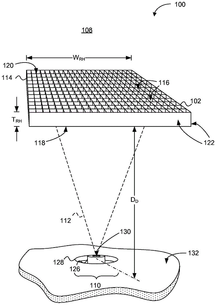
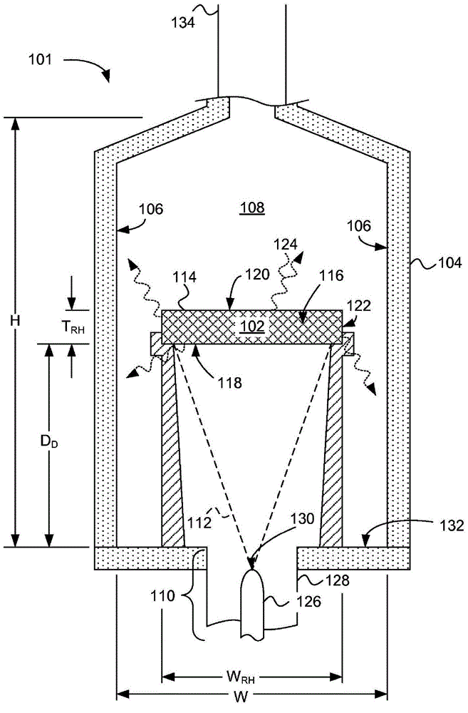
[0157] Figure 12 is a schematic diagram of an experimental setup 1200 used to determine the effect of dilution distance between a fuel nozzle and a perforated reaction stabilizer, according to one embodiment. In the experimental setup, the test ignition was carried out under the following conditions:

[0158] The fuel is methane.

[0159] Fuel pressure varies but is always around 12 psi.

[0160] The fuel nozzle (pinhole) diameter is 0.11".

[0161] The airlock in the exhaust stack was always "closed" with about 1 / 4" of clearance around the airlock. The stack size was about 12" square. The 1 / 4" gap allows the exhaust flue damper to never fully close.

[0162] The air source (inlet air) was natural draft and confined in a 3" hole positioned concentrically with the fuel nozzle tube occupying 1 / 4" around the center of the 3" hole.

[0163] 3% O in the stack 2 for NOx comparison.

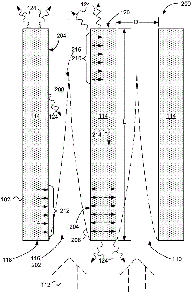
[0164] The perforated reaction stabilizer had a total thickness of 4" (L dimension). The 4" ...


PUM


Abstract

A such as a furnace or boiler includes a perforated reaction holder configured to hold a combustion reaction that produces very low oxides of nitrogen (NOx).

Description

[0001] Cross References to Related Applications [0002] This application claims U.S. Provisional Patent Application Serial No. 61 / 765,022, filed February 14, 2013, entitled "Perforated Flame Holder And Burner Including A Perforated Flame Holder" and priority to U.S. Provisional Patent Application No. 61 / 931,407, filed January 24, 2014, entitled "Low NOx Fire Tube Boiler"; In case of content conflict, it is hereby incorporated by reference in its entirety. [0003] This application is related to Attorney's Case No. 2651-172, filed February 14, 2014, entitled "PERFORATED FLAME HOLDER AND BURNER INCLUDING A PERFORATED FLAME HOLDER" No. 04; Attorney's Case No. 04, filed February 14, 2014, entitled "STARTUP METHOD AND MECHANISM FOR A BURNER HAVING A PERFORATED FLAME HOLDER" 2651-204-04; and Attorney Case No. 2651-167-04, filed February 14, 2014, entitled "SELECTABLE DILUTION LOW NOx BURNER"; Incorporated herein by reference to the extent that it does not conflict with the disclos...

Claims


Application Information

Patent Timeline
Patent Type & Authority Applications(China)
IPC IPC(8): F23D14/26F23D14/80F23C5/00
CPCF23D2207/00F23D2203/104F23D14/74F23N1/00F23N5/00F23D14/02F23D2203/102F23C5/00F23D14/26F23D14/80F23D14/145F23D2203/1023F23D11/42F23D11/448F23D2203/105F23N5/10F23D2203/1012F23D2208/10F27D11/06F23D11/446Y02E20/34Y02T50/60F23N5/265F23D14/24F23D14/84F23N2900/00F23N2221/00F23N2227/22F23C99/001F23D11/02F23D11/383F23D11/406F23D11/38F23L7/007F23N1/002F23C6/042F23C9/06F23C2201/00F23C2900/00F23N1/02
Inventor 道格拉斯·W·卡尔科夫罗伯特·E·布赖登塔尔约瑟夫·科兰尼诺克里斯多佛·A·威克洛夫
Owner 美一蓝技术公司
Why Eureka
Try Eureka