
Equipment for manufacturing three-dimensional object

A technology of three-dimensional objects and equipment, applied in the field of 3D printing, can solve the problems of no monitoring performance, no application of sintering or melting performance, no way of knowing the temperature change of molten pool, etc., and achieve the effect of improving performance and simple equipment logic

Active Publication Date: 2015-09-16
HUNAN FARSOON HIGH TECH CO LTD
View PDF8 Cites 25 Cited by
  • Summary
  • Abstract
  • Description
  • Claims
  • Application Information

AI Technical Summary

Problems solved by technology

In this monitoring method, the image of the working plane is simply collected. This image is only simple RGB (three primary color light mode) data, and the temperature change of the molten pool cannot be known, so it cannot be applied to the sintering or melting performance. Improved, no better monitoring performance

Method used


Image

  • Equipment for manufacturing three-dimensional object
  • Equipment for manufacturing three-dimensional object

Examples


Embodiment Construction

[0011] In order to make the objectives, technical solutions, and advantages of the present invention clearer, the following further describes the present invention in detail with reference to the accompanying drawings and embodiments. It should be understood that the specific embodiments described herein are only used to explain the present invention, and do not limit the protection scope of the present invention.

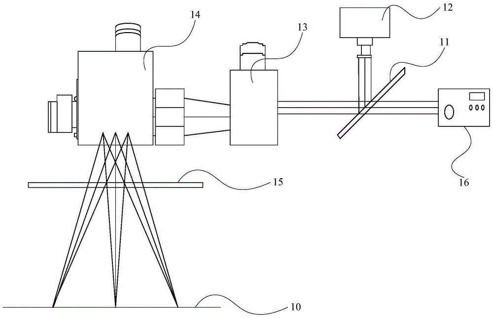
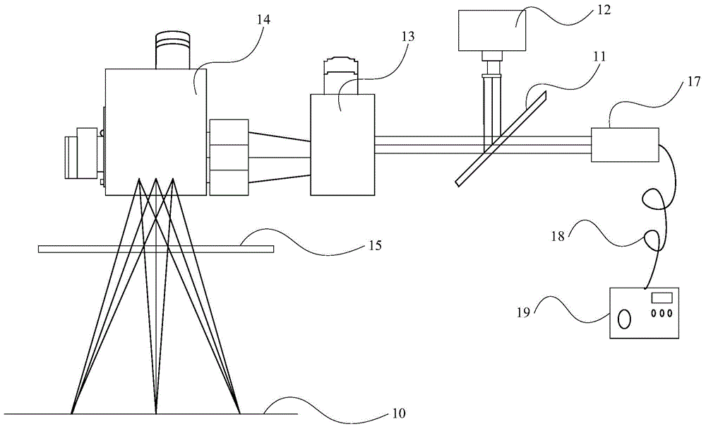
[0012] figure 1 A schematic structural diagram of a device for manufacturing a three-dimensional object in an embodiment of the present invention is shown in FIG. Such as figure 1 As shown, the equipment in this embodiment includes: a light splitting unit 11, an image monitoring device 12, a dynamic focus module 13, a galvanometer system 14, and a window mirror 15. The light splitting unit 11, the image monitoring device 12, and the dynamic focus module 13 , The galvanometer system 14 and the window mirror 15 pass between figure 1 Show the optical path to establish th...


PUM

PropertyMeasurementUnit
Wavelengthaaaaaaaaaa

Abstract

The invention relates to equipment for manufacturing a three-dimensional object. The equipment for manufacturing the three-dimensional object comprises a light splitting unit, image monitoring equipment, a dynamic focusing module, a vibration mirror system and a window mirror, wherein laser light emitted by a laser all passes through the light splitting unit, is dynamically focused by the dynamic focusing module, reaches the vibration mirror system and is focused to the working plane of three-dimensional object manufacturing equipment through the vibration mirror system and the window mirror, spontaneous radiation light of the working plane sequentially passes through the window mirror, the vibration mirror system and the dynamic focusing module, reaches the light splitting unit, is reflected by the light splitting unit and reaches the image monitoring equipment, and the image monitoring equipment monitors the temperature of a molten bath and the change of the temperature through the received spontaneous radiation light. The scheme provided by the embodiment of the invention not only realizes the online real-time monitoring of the three-dimensional object manufacturing equipment, but also can be used for the modification of parameters in a rapid forming and manufacturing process, and can improve the performance of rapid forming and manufacturing.

Description

Technical field [0001] The present invention relates to the field of 3D printing technology, in particular to a device for manufacturing three-dimensional objects. Background technique [0002] Rapid prototyping technology (also known as rapid prototyping manufacturing technology, Rapid Prototyping Manufacturing, RPM for short), also known as 3D printing, uses laser action to layer-by-layer and selectively consolidate powder materials to form three-dimensional objects. The usual steps of this method are: spread the powder to the plane of a cylinder (forming cylinder) for carrying three-dimensional objects through a powder conveying system and a powder spreading system. The laser is based on the corresponding position information of the three-dimensional object in each section. Carry out the corresponding consolidation. After the consolidation of one layer of cross-section is completed, the cylinder body is lowered to a certain height, and a new round of consolidation is carried o...

Claims


Application Information

Patent Timeline
IPC IPC(8): B22F3/105B29C67/00B33Y30/00
CPCY02P10/25
Inventor 许小曙鲍光
Owner HUNAN FARSOON HIGH TECH CO LTD
Learn More