Variational integral-discretization Lagrange model-based Buck-Boost converter modeling and nonlinear analysis method
A nonlinear analysis and converter technology, applied in instruments, special data processing applications, electrical digital data processing, etc., can solve the problems of inaccurate discrete iterative models, inaccurate nonlinear dynamic behaviors, and complex discrete iterative model operations. , to achieve the effect of reducing computational complexity and computing time
- Summary
- Abstract
- Description
- Claims
- Application Information
AI Technical Summary
Problems solved by technology
Method used
Image
Examples
specific Embodiment approach 1
[0027] Specific embodiment one: a kind of Buck-Boost converter modeling and nonlinear analysis method based on the variational integral discrete Lagrangian model of the present embodiment is specifically prepared according to the following steps:
[0028] Step 1, constructing the Euler-Lagrange function of the Buck-Boost converter;
[0029] Step 2, after discretizing the Buck-Boost Euler-Lagrangian function, constructing the Hamiltonian system equation;
[0030] Step 3. Through the Hamiltonian system equation, derive the position-momentum p of the variational integral k and p k+1 ;
[0031] Step 4, according to p k and p k+1 Establish a discrete Lagrangian model of the Buck-Boost converter;
[0032] Step 5, using the discrete Lagrangian model of the Buck-Boost converter to derive the Jacobian matrix eigenvalues of the system;
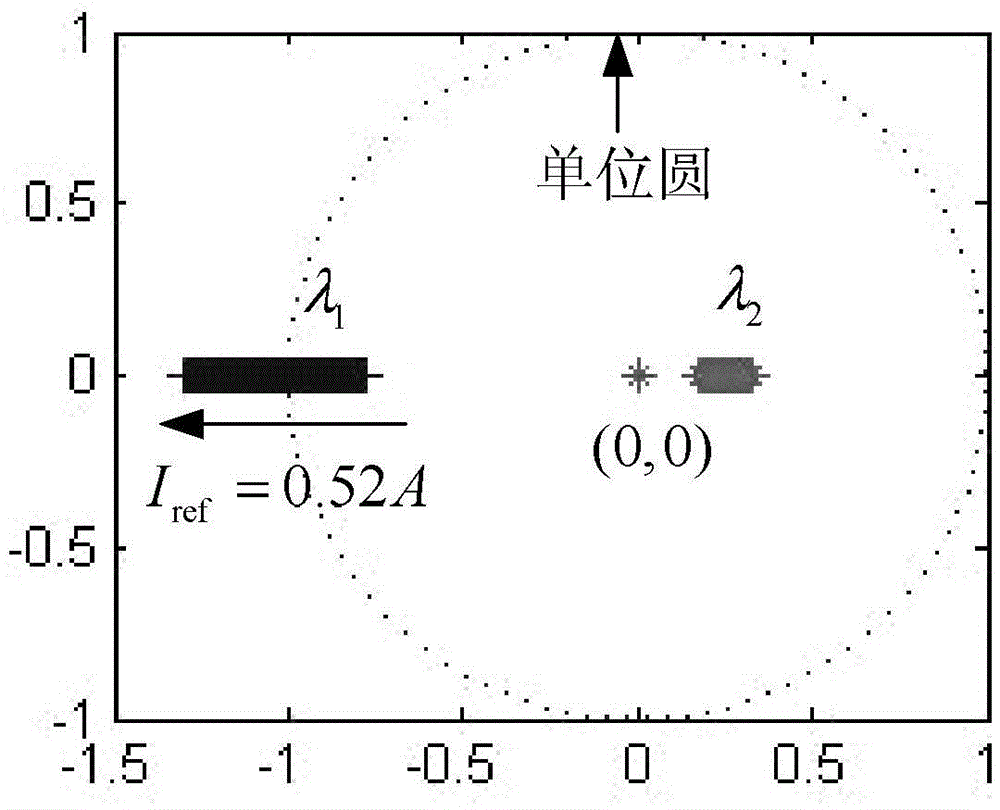
[0033] Step 6. Use the eigenvalues of the Jacobian matrix to find the nonlinear behavior of the Buck-Boost converter's stable region and the ...
specific Embodiment approach 2
[0038] Specific embodiment two: the difference between this embodiment and specific embodiment one is: the Euler-Lagrangian function of constructing the Buck-Boost converter in step one is specifically:
[0039] (1) Definition is the kinetic energy of the circuit, ν u (q C) is the potential energy of the circuit, is the dissipation function of the circuit, ν u,nc (q) is the external force function of the system, u is the control signal; when u=0, the switch is off, and when u=1, the switch is on, the specific form is as follows:
[0040] T u ( q · L ) = 1 2 L q · L 2 , v u ( q C ) ...
specific Embodiment approach 3
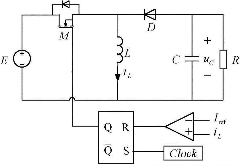
[0047] Embodiment 3: The difference between this embodiment and Embodiment 1 or 2 is that the schematic diagram of the Buck-Boost converter current mode control in Step 1 is as follows: figure 1 As shown, the current mode control of the Buck-Boost converter is specifically:
[0048] (1) All the components in the circuit are regarded as ideal devices; among them, the components in the circuit include inductors, capacitors, resistors, switching tubes, input power supplies, comparators and RS flip-flops; ideal devices have a single constant relationship Components affected by other factors such as material temperature;
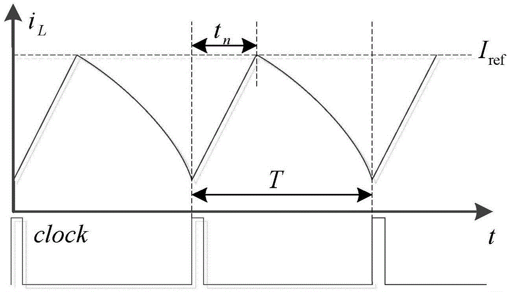
[0049] (2) Divert the inductor current i L with reference current I ref For comparison, if i L greater than I ref , then the input of the R terminal of the RS flip-flop is 1; if i L less than I ref , then the input of the R terminal of the RS flip-flop is 0;
[0050] (3) The clock signal is input through the S terminal of the RS flip-flop. If the input of ...
PUM
 Abstract
Description
Claims
Application Information
 - R&D
- Intellectual Property
- Life Sciences
- Materials
- Tech Scout
- Unparalleled Data Quality
- Higher Quality Content
- 60% Fewer Hallucinations
Browse by: Latest US Patents, China's latest patents, Technical Efficacy Thesaurus, Application Domain, Technology Topic, Popular Technical Reports.
© 2025 PatSnap. All rights reserved.Legal|Privacy policy|Modern Slavery Act Transparency Statement|Sitemap|About US| Contact US: help@patsnap.com


