Hollow coil winding equipment
A technology of winding equipment and hollow coils, which is applied in the direction of coil manufacturing, conveying filamentous materials, and thin material processing, etc., which can solve the problems of inability to start winding operations immediately, short service life of winding fixtures, and reduced practicality of winding equipment. Sex and other issues, to achieve the effect of shortening the heating time, driving stability, and humanized design
Active Publication Date: 2015-09-16
TANAC AUTOMATION
8 Cites 13 Cited by
AI-Extracted Technical Summary
Problems solved by technology
However, no matter the above two winding schemes, there are at least the following defects: in the process of winding, only one heating pair is heating the winding jig, and then the coiled wire is heated by the heating temperature of the winding jig. Heating is carried out to complete self-adhesion, and the double-ended hollow coil is finally processed. When winding the coiled wire, the coiled wire is tensioned by a tensioner or a servo motor.
The above-mentioned method can meet the production requirements to a certain extent, but the above-mentioned method also has at least the following defects: the heating process takes a long time and the winding operation cannot be started immediat...
Method used
Optimization scheme, as shown in Figure 10-11, be provided with the anti-rotation mechanism 25 that can prevent that winding jig to rotate between mounting seat 2 and winding jig 13; Driving rod 25a, the lifting driving rod 25a is connected with the lifting cylinder 25b that can drive it to lift in the vertical direction. It has an anti-rotation structure to stop the rotation. The anti-rotation structure includes a plurality of anti-rotation positioning pins 25c respectively arranged on the lifting drive rod 25a and corresponding to each of the winding jigs. In an optimized solution, a slot 13a for inserting the anti-rotation positioning pin 25c is provided on the winding jig, and the winding jig stops rotating when the anti-rotation positioning pin is inserted into the slot. The anti-rotation positioning pin 25c is fixed on the lifting drive rod 25a by the positioning pin seat, and is provided with a pin hole on the positioning pin seat. A spring located in the pin hole is sleeved, one end of the spring acts on the anti-rotation positioning pin, and the other end acts on the positioning pin seat. Each positioning pin seat 25f is respectively provided with an anti-collision lifting column 25d that can be forced to move downward when the spring is compressed, and a sensor 25e aligned with the anti-collision lifting column is provided at one end of the lifting drive rod. When the anti-rotation positioning pin cannot be inserted in the slot, the spring is compressed so that the anti-collision lifting column descends. After the sensor detects the falling anti-collision lifting column, it sends a signal to th...
Abstract
The invention relates to hollow coil winding equipment, which solves the technical problem that the heating time is long and the cost is high in the prior art. The hollow coil winding equipment comprises a bobbin unit, a stand arranged at one side of the bobbin unit and a plurality of winding fixtures. A mounting base is arranged on the stand. A plurality of main shafts which correspond to the winding fixtures one to one and which are connected with the winding fixtures in a rotary manner are arranged on the mounting base. A plurality of counter shafts which correspond to the winding fixtures one to one and which can be used for driving the winding fixtures to rotate are arranged on the mounting base. The equipment further comprises a heating system which can be used for heating the two ends of wound coils and the wound coils wound on the winding fixtures. The equipment further comprises a tension control system for enabling the two ends of the wound coils to have constant tension while the wound coils are continuously wound on the winding fixtures. The invention has the advantages that the hollow coil winding equipment could greatly reduce the heating time, and is low in cost and stronger in practicability.
Application Domain
Filament handlingCoils manufacture
Technology Topic
Heating systemHeating time +4
Image
Examples
- Experimental program(2)
Example Embodiment
[0051] Example one
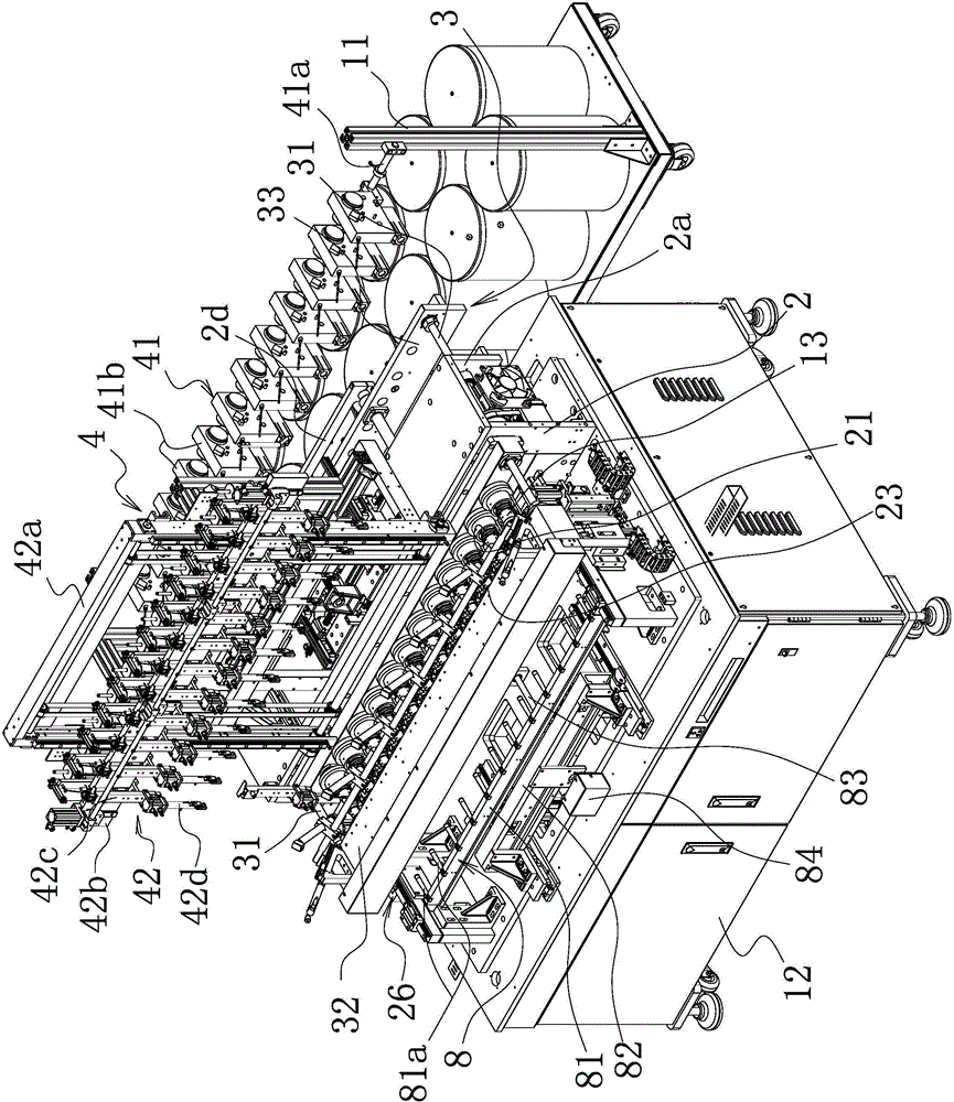
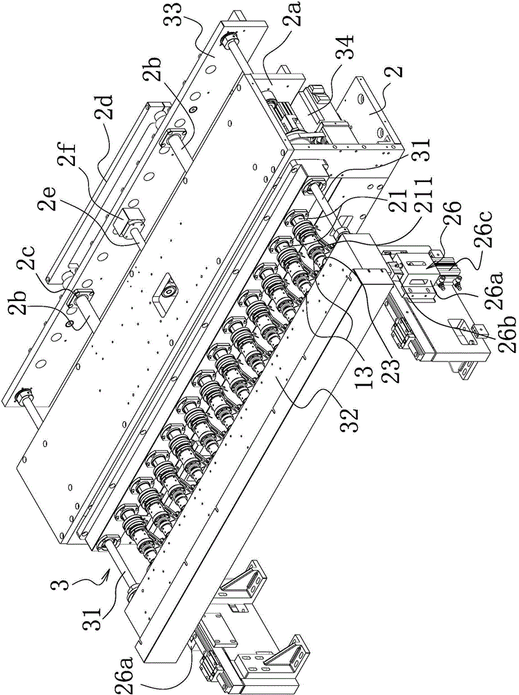
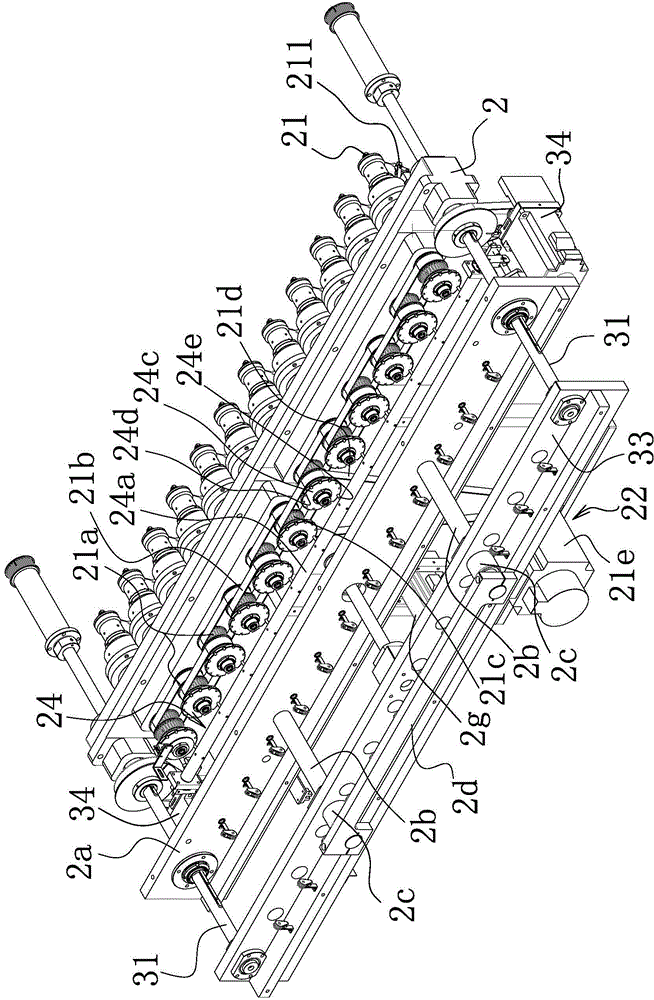
[0052] Such as Figure 1-4 As shown, the air-core coil winding equipment includes a bobbin unit 11 and a stand 12 located on one side of the bobbin unit 11, and a number of winding jigs 13 formed by the cooperation of a female core mold and a male core mold. A mounting seat 2 is provided on the mounting seat 2 with a number of spindles 21 corresponding to the winding jig 13 one-to-one and connected to the winding jig 13 in rotation. The spindle 21 is driven by a spindle that can drive it to rotate. The mechanism 22 is connected, and the spindle drive mechanism 22 includes a spindle drive pulley 21a arranged on each spindle 21 and a transmission timing belt 21b surrounding the spindle drive pulley. At least one of the spindles is provided with The driven driving pulley 21c is connected to the main driving pulley 21f provided on the main shaft driver 21e through the driving timing belt 21d. The spindle driver 21e is a drive motor.
[0053] Secondly, such as Figure 5-6 As shown, a spindle brake mechanism 24 that can stop the spindle 21 is provided between the mounting seat 2 and the spindle 21; the spindle brake mechanism 24 includes a rotating rod 24a located outside one end of the spindle 21, the rotating rod The two ends of 24a are respectively connected to the brake cylinder 24b by a linkage structure. A brake structure is provided between the rotating rod 24a and the main shaft 21 to stop the rotation of the main shaft 21 when the rotating rod rotates to a set position. The braking structure includes a rotating disc 24c arranged on each main shaft 21 and rotating synchronously with the main shaft. The outer edge of the rotating disc is provided with a number of notches 24d evenly distributed on the circumference, and a plurality of rotating discs are provided on the rotating rod. The brake pins 24e are in one-to-one correspondence and can be locked in the notches.
[0054] Such as Figure 1-3 with Figure 7-8 As shown, the mounting base 2 is also provided with a secondary shaft 23 corresponding to the winding jig 13 and capable of driving the winding jig 13 to rotate, and the mounting base 2 is provided with a secondary shaft 23 capable of driving the winding jig 13 The shaft 23 moves along its axial direction so that the female core mold and the male core mold of the winding jig 13 are separated from or matched with each other and can drive the clutch drive transmission mechanism 3 of the secondary shaft 23 to rotate. Specifically, the clutch drive transmission mechanism 3 of this embodiment includes two drive shafts 31 respectively passing through the two ends of the mounting base 2. The drive shaft 31 is rotatably connected with the mounting base 2 and the drive shaft 31 can be relatively mounted The seat 2 reciprocates along the axial direction of the drive shaft 31, a translation seat 32 slidably connected to the mounting seat 2 is provided between the corresponding ends of the two drive shafts 31, and the secondary shafts 23 are respectively rotatably arranged on the translation seat 32 Above, the drive shaft 31 is connected to a servo rotary drive structure that can drive the drive shaft 31 to rotate, and the drive shaft 31 and the counter shaft 23 are connected by a transmission structure. The drive shaft 31 is also connected to the drive shaft 31 along The axial drive structure of the axial reciprocating movement is connected. The servo rotation drive structure includes a servo motor 34. The servo motor 3 is connected to the drive shaft 31 through a timing belt.
[0055] The axial drive structure includes a drive plate 33 arranged between the corresponding ends of the two drive shafts 31, and the drive shaft 31 and the drive plate 33 are rotationally connected between the drive plate 33 and the mounting seat 2. An axial guide structure is provided, and the axial guide structure includes a thread guide seat 2a arranged on the mounting seat 2, and the drive shaft 31 passes through the thread guide seat. The drive shaft and the thread guide seat 2a The seat is rotatably connected and the drive shaft can move back and forth along the axis of the drive shaft relative to the thread guide seat. Two guide posts 2b are provided on the thread guide seat, and two guide posts 2b are provided on the drive plate 33. The guide column sleeves 2c slidably connected with the guide column 2b are inserted one by one, and the guide columns 2b are inserted into the guide column sleeve 2c. Secondly, a limit plate 2d is provided at the corresponding end of the two guide posts 2b away from the thread guide seat.
[0056] In an optimized solution, the driving board 33 of this embodiment is connected to a horizontal driving structure that can push it to reciprocate in the horizontal direction. Specifically, the horizontal drive structure here includes at least one screw 2e arranged on the thread guide seat 2a, and the drive plate is provided with a screw sleeve 2f for inserting the screw and connecting with the screw thread. The screw is connected to a screw drive motor 2g that can drive the screw to rotate. In addition, the above-mentioned transmission structure includes a countershaft pulley 35 arranged at one end of each countershaft 23 away from the main shaft 21, and a part of the countershaft pulleys of the plurality of countershaft pulleys is surrounded by one of the two drive shafts 31. The first synchronous belt 36 connected to one drive shaft is surrounded by a second synchronous belt 37 connected to the other of the two drive shafts on the remaining countershaft pulleys. The translation base 32 is provided with a first tensioning wheel meshingly connected with the first timing belt 36, and the translation base 32 is also provided with a second tensioning wheel meshingly connected with the second timing belt 37.
[0057] Optimization plan, such as Figure 10-11 As shown, between the mounting seat 2 and the winding jig 13, there is a rotation stop mechanism 25 that can prevent the winding jig from rotating; the rotation stop mechanism 25 includes a horizontally arranged lifting drive rod 25a, the lifting drive rod 25a and the drive The lifting cylinder 25b that lifts in the vertical direction is connected, and the lifting drive rod 25a is provided with a rotation stop structure that can stop the winding jig from rotating when the lifting drive rod 25a moves to a set position. The anti-rotation structure includes a plurality of anti-rotation positioning pins 25c respectively arranged on the lifting drive rod 25a and corresponding to the winding jigs. In an optimized solution, the winding jig is provided with a slot 13a into which the rotation preventing positioning pin 25c is inserted, and the winding jig stops rotating when the rotation preventing positioning pin 25c is inserted into the slot. The anti-rotation positioning pin 25c is fixed on the lifting drive rod 25a through a positioning pin seat. A pin hole is provided on the positioning pin seat. The anti-rotation positioning pin 25c is vertically arranged and the lower end is inserted in the pin hole. A spring is sleeved in the pin hole, one end of the spring acts on the anti-rotation positioning pin, and the other end acts on the positioning pin seat. Each positioning pin base 25f is respectively provided with an anti-collision lifting column 25d that can be forced to move downward when the spring is compressed, and a sensor 25e aligned with the anti-collision lifting column is provided at one end of the lifting driving rod. When the anti-rotation positioning pin cannot be inserted into the slot, the spring is compressed to lower the anti-collision lifting column. The sensor detects the falling anti-collision lifting column and sends a signal to the lifting cylinder 25b to stop the action, that is, an alarm and Early warning signal to ensure the safety of equipment operation.
[0058] Secondly, such as figure 2 As shown, the mounting seat 2 is provided with a translation seat locking mechanism 26 that can stop the translation seat 32 from moving. The translation base locking mechanism 26 includes positioning bases 26a respectively provided at both ends of the translation base 32, and a movable locking block 26b is provided on the positioning base 26a, and the movable locking block and the movable locking block can be driven toward the translation base 32. The drive cylinder 26c, which moves sideways to connect the translation base 32, is connected. The translation seat locking mechanism 26 can ensure the thickness of the hollow coil and improve the quality of the product.
[0059] Such as Figure 12-15 As shown, the device also includes a tension control system 4 that can make both ends of the coiled wire a have a constant tension when the coiled wire a is continuously wound on the winding jig 13. The tension control system 4 includes a first tension control mechanism 41 provided on the spool unit 11 and a second tension control mechanism 42 provided on the mounting base 2.
[0060] Specifically, the first tension control mechanism 41 of this embodiment includes a mounting rod 41a provided on the bobbin unit 11, and a number of tensioners 41b corresponding to the main shaft 21 are provided on the mounting rod 41a. The main shaft is provided with a thread passing channel. One end of the thread passing channel is the wire inlet end and the other end is the wire outlet end. The main shaft is provided with a fly fork arm 211 that rotates synchronously with the main shaft. The coiled wire on the spool unit 11 passes through the tension The tensioner 41b enters the thread passage hole of the thread guide seat, and then enters the thread passage of the main shaft and is output from the fly fork arm 211, and finally winds one end of the coiled wire on the winding jig through the rotation of the main shaft.
[0061] Secondly, the second tension control mechanism 42 includes a movable frame 42a provided on the mounting base 2, and the movable frame 42a is connected to a multi-directional drive structure that can drive it to move in the longitudinal and lateral directions. The multi-directional drive structure includes a lateral The screw is combined with the driving structure of the transverse screw sleeve and the longitudinal screw with the longitudinal screw sleeve, and the transverse screw and the longitudinal screw are respectively connected with the screw motor. The movable frame 42a is provided with a lifting and moving arm 42b, and a number of lifting and moving blocks 42c are provided on the lifting and moving arm 42b. Each lifting and moving block 42c is provided with a clamping and disconnecting device 42d. The movable frame 42a There is a first lifting drive capable of driving the lifting and moving arm 42b to move downward so that the clamping and breaking device 42d clamps one end of the wound wire and can move the lifting and moving arm 42b back Mechanism 42e, and the wound wire can be lifted upward along with the lifting moving arm 42b. Between the lifting moving arm 42b and the lifting moving block 42c, when the wire is wound and forcing the lifting moving block When 42c moves downward, the constant tension control structure 42f can make the wire have a constant tension. Specifically, such as Figure 14 As shown, the constant tension control structure 42f here includes a tension spring 42k, one end of the tension spring 42k is connected to the lifting movement arm 42b, and the other end is connected to the lifting movement block 42c. During the winding process, the tension spring 42k is continuously stretched to generate a constant tension.
[0062] In an optimized solution, the above-mentioned lifting and moving arm 42b is provided with a horizontal driving rod 42g that is slidably connected to the lifting and moving arm 42b, and the lifting and moving blocks 42c are respectively fixed on the driving rod 42g and slidably connected to the lifting and moving arm 42b, A second lifting driving mechanism 42h capable of driving the driving rod 42g to move in the vertical direction is provided on the lifting moving arm 42b.
[0063] Furthermore, the above-mentioned first lifting driving mechanism 42e includes two driving shafts 421 spaced up and down, and both ends respectively pass through the movable frame 42a. Any one of the two driving shafts 421 is driven by a belt. The structure is connected with a servo drive motor 422 that can drive it to rotate. The drive shafts 421 are connected by two synchronous wheel transmission belts 423, and the lifting and moving arms 42b are arranged on the two synchronous wheel transmission belts 423. Secondly, vertical guide rails 424 are arranged vertically on both sides of the movable frame 42a, and the lifting and moving arm 42b is arranged on the vertical guide rail 424 and slidably connected with the vertical guide rail 424.
[0064] The second lifting driving mechanism 42h includes second drivers 425 arranged at both ends of the lifting moving arm 42b. The lifting moving arm is provided with a number of second guide rails arranged at intervals, and the driving rod 42g is provided with a number of The two guide rails are one-to-one corresponding and slidingly connected sliding blocks, and the second driver is connected with the sliding blocks located at both ends of the driving rod.
[0065] In order to further improve the winding quality, such as Figure 16-18 As shown, the device also includes a heating system that can respectively heat the coiled wire a coiled on the winding jig 13 and the two ends of the coiled wire a. Specifically, the heating system here includes a heating system that is arranged on the main shaft 21 and can be continuously coiled to the winding jig 13 when one end of the coiled wire a is rotated along the circumference of the winding jig 13 to be wound on the winding jig 13 The rotary preheating mechanism 5 on the tool 13 for real-time heating of the coiled wire a is an optimized solution. The rotary preheating mechanism 5 here includes a rear ring end sleeved on the main shaft 21 and rotationally connected to the main shaft 21 The cover 51 is also sleeved on the main shaft 21 with a front annular end cover 52 which is movably and sealedly connected with the rear annular end cover 51 in a circumferential direction, and an annular air groove 53 is provided between the rear annular end cover 51 and the front annular end cover 52, An air inlet 51a communicating with the annular air groove 53 is provided on the rear annular end cover 51, an air outlet 52a communicating with the annular air groove 53 is provided on the front annular end cover 52, and an outlet pipe is connected to the air outlet 52a 52b. The air outlet portion of the air outlet pipe 52b is aligned with the coiled wire wound on the winding jig via the fly fork arm.
[0066] Secondly, such as Figure 19 As shown, the mounting seat 2 is provided with the winding jig 13 when the other end of the coiled wire a is continuously wound and the coiled wire a is coiled on the winding jig 13 to continuously coil to the winding jig 13 The preheating device 6 on 13 for real-time heating of the coiled wire a, the preheating device 6 includes a hot air generator 61, and at least one exhaust pipe 62 is connected to the hot air generator 61. The hot air generators 61 are sequentially arranged on the horizontally arranged preheating moving rods, and the preheating moving rods 63 are connected to a preheating driving structure capable of driving the preheating moving rods to move obliquely in the vertical direction. An air guiding pipe 64 is connected between the hot air generator and the exhaust pipe, and the inner diameter of the air guiding pipe is larger than the inner diameter of the exhaust pipe. When the clamping and breaking device 42d is lowered to the preset height, the thread end of the coiled wire is taken and then lifted to the set height. When the winding jig 13 is continuously wound and the clamped breaking device 42d is raised When one end of the coiled wire is used, the exhaust duct 62 is aligned with the raised end of the coiled wire.
[0067] In addition, such as Figure 20 As shown, the mounting base 2 is also provided with a heating device 7 capable of heating the coiled wire a coiled on the winding jig 13. The heating device 7 includes an air supply pipe 71 which is connected to a hot air source. The air supply pipe 71 is provided on a lifting rod 72 arranged horizontally. The lifting rod 72 can be moved vertically and horizontally.
[0068] Because the rotary preheating mechanism is installed, the coiled wire rotating along the circumferential direction of the winding jig can be heated in real time (synchronous rotation), and the other end of the coiled wire can be heated in real time due to the preheating device. Since the heating device is set to heat the coiled wire wound on the winding jig in real time, preheating not only shortens the heating time, but also improves the heating effect, making the heating more uniform, and also improves the product The processing quality and the stability of later use further improve the practicability of the winding machine, which is in line with the current development trend of social technology. Secondly, if there is no preheating, the temperature of the winding fixture is higher than the heating temperature of the coiled wire during the winding operation of the winding equipment, and the addition of the heating system of this embodiment can reduce the winding fixture Temperature, thereby prolonging the service life of the winding jig. At the same time, compared with only one heating (the total current output by the multi-axis is higher and the temperature is higher), the addition of the heating system of this embodiment can reduce the total temperature, that is The power is reduced, and the design is more humanized.
[0069] Further, as figure 1 As shown, in order to improve the degree of machine automation and the production efficiency of the machine, the mounting base 2 is provided with a reclaiming mechanism 8 that can obtain the hollow coil from the winding jig 13 when the winding is completed; specifically, the reclaiming mechanism 8 includes a reclaiming rod 81 arranged on the mounting seat, and a plurality of reclaiming rods 81a corresponding to the winding jig are provided on the reclaiming rod 81, and the reclaiming rod 81 is set on the reclaiming rod. As for the lifting mechanism, the reclaiming lifting mechanism is connected with a horizontal reclaiming driving mechanism that can drive it to reciprocate in the horizontal direction. The horizontal reclaiming drive mechanism includes a reclaiming base 82 slidably connected to the mounting base. The reclaiming base 82 is provided with a reclaiming screw sleeve, and the mounting base is provided with a reclaiming screw sleeve inserted in the reclaiming screw sleeve and threadedly connected with the reclaiming screw sleeve. The reclaiming screw 83, the reclaiming screw 83 is connected to the reclaiming rotating motor 84, the reclaiming rod 81 is slidably connected to the reclaiming base 82, and at least one connecting to the reclaiming rod 81 is provided on the reclaiming base 82 cylinder.
[0070] Such as Picture 9 As shown, the clamping and breaking device 42d includes a clamping sleeve 426. One end of the clamping sleeve 426 is provided with a static positioning surface 427. The clamping sleeve 426 is provided with a static positioning surface or a distance away from the static positioning surface so as to be The coiled wire clamps or releases the dynamic pressure portion 428 of the coiled wire. The dynamic pressure portion is also provided with a cutter 429 that can cut the wire synchronously when the wire is clamped. The dynamic pressure portion and the driving dynamic pressure The clamping and disconnecting cylinders 430 close to the static positioning surface or away from the static positioning surface are connected. The clamping and breaking cylinder 430 is connected to the dynamic pressure part 428 through the jack 431 inserted in the clamping sleeve 426.
[0071] The working principle of this embodiment is as follows: when the clamping and breaking device 42d pulls the coiled wire a, the spool unit 11 releases the wire, and the coiled wire sequentially passes through the tensioner and the thread guide seat 2a into the passing of the main shaft 21 The wire passes and is output from the fly fork arm, and then the translation seat 32 is driven by the drive shaft 31 to make the secondary shaft 23 close to the main shaft 21 and make the female core mold of the winding jig 13 cooperate with the male core mold, and then The drive shaft 31 rotates radially and drives the secondary shaft 23 to drive the winding jig 13 to rotate. At the same time, the main shaft drive mechanism 22 drives the main shaft to rotate so that the middle part of the coiled wire is pre-wound on the winding jig 13. During the winding process , The coiled wire is heated by the rotary preheating mechanism 5, the preheating device 6 and the heating device 7.
[0072] When the first winding is completed, the coiled wire material is cut by the clamping and breaking device 42d and the end of the next winding wire is clamped, and then the auxiliary shaft 23 is moved away from the main shaft 21 under the axial drive of the drive shaft 31 Thus, the female core mold and the male core mold are separated, the wound hollow coil is removed by the material taking mechanism 8, and the above steps are repeated to enter the next winding.
Example Embodiment
[0073] Example two
[0074] Such as Figure 15 As shown, the structure and principle of this embodiment are basically the same as those of the first embodiment, and will not be repeated here. The difference is that the constant tension control structure 42f includes a counterweight 42p connected to the lifting and moving block 42c. The top of the lifting moving block 42c is provided with a movable pulley 42q. The counterweight 42p and the lifting moving block 42c are connected by a rope 42s passing through the moving pulley 42q. A number of fixed pulleys are provided on the lifting moving block 42c.
PUM


Description & Claims & Application Information
We can also present the details of the Description, Claims and Application information to help users get a comprehensive understanding of the technical details of the patent, such as background art, summary of invention, brief description of drawings, description of embodiments, and other original content. On the other hand, users can also determine the specific scope of protection of the technology through the list of claims; as well as understand the changes in the life cycle of the technology with the presentation of the patent timeline. Login to view more.
Similar technology patents
Dishwashing machine
Owner:FOSHAN SHUNDE MIDEA WASHING APPLIANCES MFG
Chemical vapor deposition (CVD) method adopting microwave heating mode
Owner:NORTHEASTERN UNIV
Plastic extrusion mold
Owner:NINGBO KANGRUN MACHINERY TECH
Classification and recommendation of technical efficacy words
- low power
- shorten heating time
Electric field sensor
Owner:BAE SYST INFORMATION & ELECTRONICS SYST INTERGRATION INC
Apparatus and method of wireless data transmission
Owner:GEBRERIT INT
Modification of column fixed pattern column noise in solid state image sensors
Owner:STMICROELECTRONICS SRL
Low-power surveillance sensor
Owner:HONEYWELL INT INC
In-situ oil extraction method for oil shale
Owner:CHINA PETROLEUM & CHEM CORP +1
Plasma reaction chamber and plasma device with same
Owner:BEIJING NAURA MICROELECTRONICS EQUIP CO LTD
Internal-circulation bulk curing barn realizing complementation of multiple energies
Owner:HUNAN UNIV OF SCI & TECH