Rotary clamp equipment for manipulator

A technology of clamping equipment and manipulators, applied in welding equipment, auxiliary welding equipment, metal processing equipment, etc., to achieve the effect of improving welding quality and work efficiency, improving work efficiency, and reasonable structure

Inactive Publication Date: 2015-09-23
天津鑫泰博弈科技有限公司
View PDF0 Cites 0 Cited by
  • Summary
  • Abstract
  • Description
  • Claims
  • Application Information

AI Technical Summary

Problems solved by technology

Make the welding consistency of various special-shaped parts high and improve the assembly performance of the whole machine

Method used


Image

  • Rotary clamp equipment for manipulator
  • Rotary clamp equipment for manipulator
  • Rotary clamp equipment for manipulator

Examples


Embodiment Construction

[0014] The present invention will be further described in detail below through the specific examples, the following examples are only descriptive, not restrictive, and cannot limit the protection scope of the present invention with this.

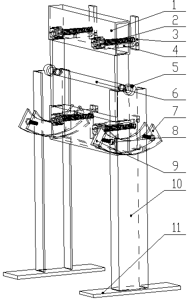
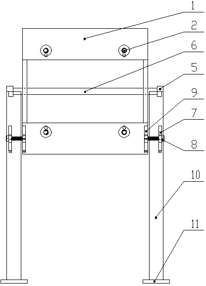
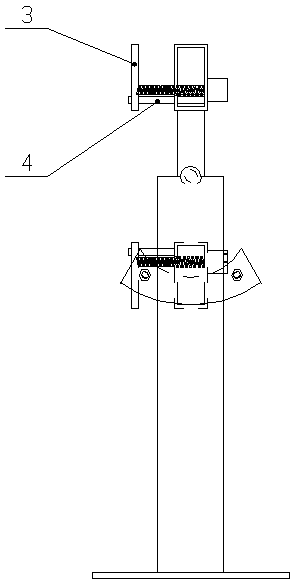
[0015] A rotary clamping device for a manipulator includes a fixed frame assembly, a frame 10, a locking fixed plate 7, a locking bolt 8, and an anchor 11, wherein the fixed frame assembly includes a fixed frame 1, a clamping bolt 2, and a clamping claw 3 , guide rod 4, shaft 6, bearing 5 and adjustment plate 9, the fixed frame 1 is a rectangle welded by square tubes, a shaft 6 is fixed in the middle, bearings 5 ​​are installed at both ends of the shaft 6, and the upper and lower parts of the fixed frame 1 Clamping bolts 2 and guide rods 4 are symmetrically arranged on the square tube, and the clamping claw 3 can move along the guide rod 4 driven by the clamping bolts 2 . The locking fixing plate 7 is welded on the frame 10, the locking bolt...


PUM


Abstract

The invention relates to rotary clamp equipment for a manipulator. The rotary clamp equipment comprises a fixing frame component, a rack, locking fixing plates, adjustment plates, locking bolts and foundations, wherein the locking fixing plates are weld on the rack; the locking bolts are mounted on the locking fixing plates in a threaded connection manner; the foundations are welded below the rack; the fixing frame component is mounted on the rack via bearings in a rotary manner; gripper jaws can clamp a workpiece by adjusting clamp bolts; the fixing frame component is rotated to an appropriate angle and then the locking bolts are locked ; and the equipment can be matched with the manipulator for operation at any angle. The rotary clamp equipment for the manipulator reduces labor intensity of a worker, improves product quality, and lowers labor cost as work to be accomplished by three persons originally can be accomplished only by one person at present; more appropriate gripper jaws can be replaced according to different workpiece shapes at the same time; the locking angle is adjusted by self weight and inertia of the workpiece; no electric energy is consumed; and the equipment is energy-saving, environmentally-friendly, safe and reliable and reduces work injuries.

Description

technical field [0001] The invention relates to the technical field of agricultural machinery, in particular to a rotary clamping device for a manipulator. [0002] Background technique [0003] At present, in the manufacturing process of agricultural machinery, most of the manipulators are used to complete the manufacture of parts with complex shapes, and the mechanical parts with complex shapes are manually operated in each process and then welded by the manipulator. Due to the instability of the manual operation of the workpiece , it is easy to cause the phenomenon that the welding seam is not in place, the welding is not strong, etc., and even the performance of the whole machine is different. Some fixtures are designed according to the shape of a certain part, and because the structure of agricultural machinery is complex, the shape is different, and the replacement is fast. Waiting to make a large amount of clamps have to be discarded, causing a lot of waste, increasi...

Claims


Application Information

Patent Timeline
Patent Type & Authority Applications(China)
IPC IPC(8): B23K37/04
CPCB23K37/047
Inventor 张瑞金李卫华赵旭
Owner 天津鑫泰博弈科技有限公司
Why Eureka
Try Eureka