Vacuum chuck manipulator paw

A technology of vacuum suction cups and mechanical grippers, applied in the field of industrial manufacturing and mechanical equipment, can solve the problems that mechanical grippers cannot play an effective role, the opening angle of the grippers is limited, and the size of the grippers has a great influence, so as to achieve ingenious design and easy operation , good practical effect

Active Publication Date: 2015-09-23
KUNMING UNIV OF SCI & TECH
View PDF6 Cites 17 Cited by
  • Summary
  • Abstract
  • Description
  • Claims
  • Application Information

AI Technical Summary

Problems solved by technology

However, the opening angle of the gripper is limited, and the volume of the grasped object is greatly affected by the siz

Method used


Image

  • Vacuum chuck manipulator paw
  • Vacuum chuck manipulator paw
  • Vacuum chuck manipulator paw

Examples


Embodiment 1

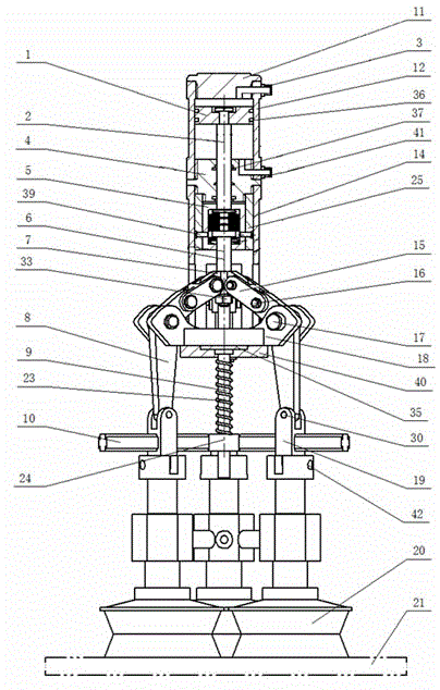
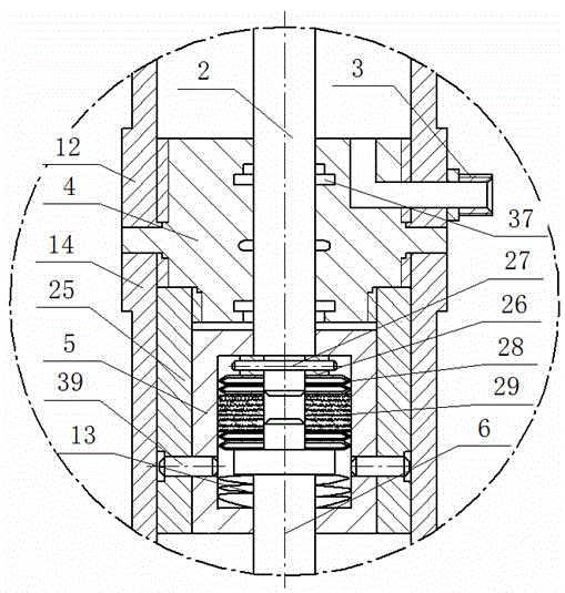
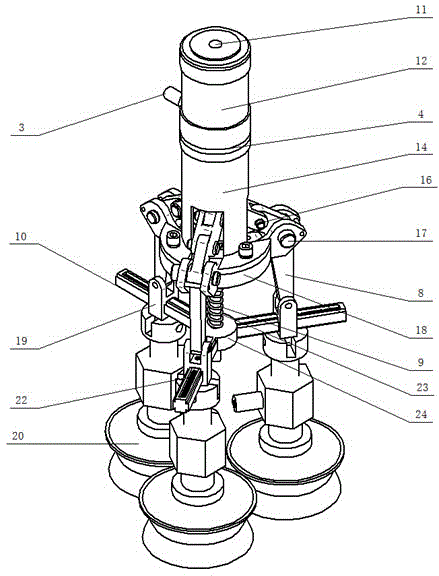
[0035] Example 1: Such as Figure 1-11As shown, the vacuum suction cup manipulator includes piston 1, piston rod 2, pipe joint I3, front cylinder cover 4, sleeve 5, push-pull rod 6, push-pull head 7, three knuckles 8, connecting rod 9, suction cup chute 10. Rear cylinder cover 11, cylinder barrel 12, slack spring 13, connecting seat 14, hinge 15, hinge shaft 16, knuckle shaft 17, mounting seat 18, movable hand frame 19, vacuum sucker 20, pull-back spring 22, spring 23. Connecting ring 24, sleeve connecting seat 25, piston rod fixing plate 26, piston pin 27, disc spring set, friction plate 29, movable hand frame pin 30, spring stopper 31, stopper screw 32, lock nut 33. Piston nut 34, pressure plate 35, sealing ring 36, sealing ring 37, connecting rod fixing plate 40, pipe joint II 41, hinge pin 42; wherein the cylinder barrel 12 is connected with the external thread on the upper end of the front cylinder cover 4, and the rear cylinder cover 11 is connected with the internal...

Embodiment 2

[0041] Embodiment 2: The structure of this embodiment is the same as that of Embodiment 1, except that four knuckles 8 are set, which are distributed in the circumference range at an angle of 90°; corresponding to the installation location;

[0042] Described vacuum sucker 20 is installed on the movable arm rest 19 by hinge pin 42, and vacuum sucker can select standard sucker for use according to the object 21 types to be lifted; The frames are fixed together in series, and accordingly the number of vacuum suction cups 20 is consistent with the number of movable hand frames 19 .

[0043] This solution obtains greater and more stable adsorption force by increasing the number of vacuum chucks 20 and changing their layout, and the size and weight of the object to be lifted 21 are doubled.


PUM


Abstract

The invention discloses a vacuum chuck manipulator paw which comprises a piston, a piston rod, a pipe connector I, a front cylinder cover, a sleeve, a push-pull rod, a push-pull rod head, more than three knuckles, a connecting rod, a chuck sliding groove, a rear cylinder cover, a cylinder, a relaxation spring, a connecting seat, a hinge, a hinge shaft, a knuckle shaft, a mounting seat, a movable hand rack, a vacuum chuck, a return spring, a spring, a connecting ring, a sleeve connecting seat, a piston rod fixing plate, a piston pin, a disc spring slice group, a friction plate, a movable hand rack pin, a spring stopper, a stopper locking nut, a piston nut, a pressing plate, a sealing ring, a seal ring, a connecting rod fixing plate and a pipe connector II. When the cylinder charges air or discharges air, the push-pull rod is driven to move downwards or upwards, the manipulator paw opens or shrinks, the return spring is compressed or rebounds along with the manipulator paw, so that the chuck horizontally slides on an X plane and a Y plane and vertically moves in a Z direction and is matched with an external big arm to move, blocks with different sizes can be caught and taken, and the requirements of actual production are met.

Description

technical field [0001] The invention relates to a vacuum sucker mechanical claw, which belongs to the technical field of mechanical equipment and is mainly used in the field of industrial manufacturing. Background technique [0002] Chinese patent CN104002304A discloses a "new pneumatic manipulator". Its mechanical claws and knuckles are directly mounted on the claw mounting base through hinges. Compared with traditional mechanical claws, it has the advantages of compact structure and sensitive response. However, the opening angle of the gripper is limited, and the volume of the grasped object is greatly affected by the size of the gripper itself, so when the grasped object is large or flat, the mechanical gripper cannot play an effective role. [0003] The vacuum suction cup manipulator uses the suction principle of the vacuum pump, and uses the manipulator instead of manual feeding, which is safe, reliable, high in efficiency, low in cost and good in practicability. Cont...

Claims


Application Information

Patent Timeline
IPC IPC(8): B25J15/06
Inventor 王学军朱登磊范景伟杨杰董鑫
Owner KUNMING UNIV OF SCI & TECH
Why Eureka
Try Eureka