Axial-flow type thermoelectric device

A thermoelectric device and axial flow technology, which is applied to gas turbine devices, motor starting for engines, combined combustion mitigation, etc., can solve the problems of restricted performance, limited thermoelectric conversion efficiency, and inability to configure generators for aviation micro-turbojet engines. Achieve the effect of improving energy efficiency, improving battlefield survivability, and maintaining power supply capacity

Active Publication Date: 2015-09-23
BEIJING LIANGMING TONGCHUANG WATER TREATMENT EQUIP DEV CENT
View PDF7 Cites 4 Cited by
  • Summary
  • Abstract
  • Description
  • Claims
  • Application Information

AI Technical Summary

Problems solved by technology

Although the existing thermoelectric devices using turbo combustors have sufficient energy utilization, they still have the following shortcomings in a relatively closed and narrow space: the structure of the aviation micro turbojet engine and engine turbocharger cannot be configured with a higher power Generator, thermoelectric conversion efficiency is limited, which restricts its performance

Method used


Image

  • Axial-flow type thermoelectric device
  • Axial-flow type thermoelectric device

Examples


Embodiment 1

[0029] It can be used in a relatively small or closed space as a heat source and power source, such as a heating power generation device in a tank or an armored vehicle.

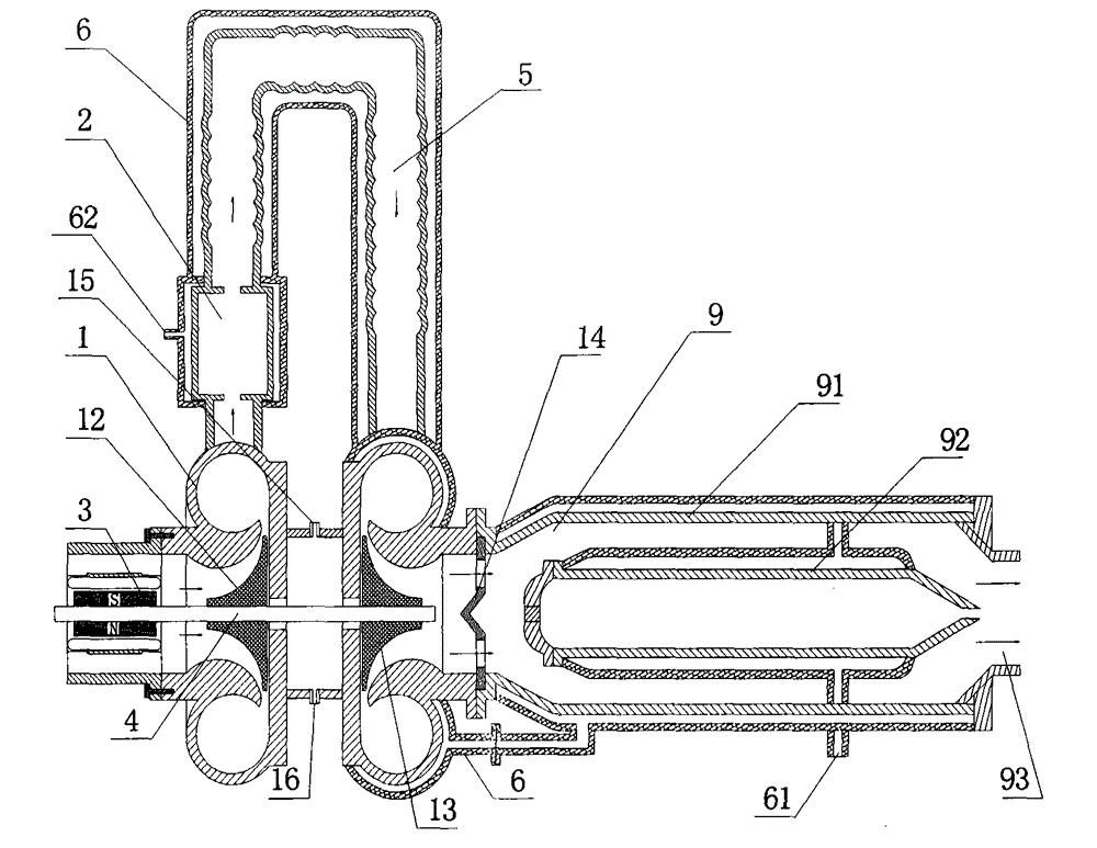
[0030] as attached figure 1 Shown, transform on the basis of the turbocharger of existing automobile engine, thus constitute the air compressor and the micro-turbine turbine of this embodiment; Combustion chamber 2 is provided between compressor 1 and micro-gas turbine 13 , the compressor outlet is communicated with the combustion chamber, and the combustion chamber hot air outlet is communicated with the micro-turbine turbine inlet through the flame conduit 5, which becomes the turbine burner of the present embodiment;

[0031] The heat exchanger 9 is a double-layer heat exchanger, and the inner heat exchange layer 92 is placed in the inner cavity of the outer heat exchange layer 91; the air inlet of the heat exchanger 9 communicates with the air outlet of the turbine burner;

[0032] The starter generator...

Embodiment 2

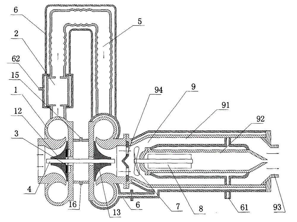
[0038] as attached figure 2 As shown, the basic structure is the same as in Embodiment 1.

[0039] An axial power turbine 7 and a generator 8 are installed in the heat exchanger, the axial power turbine 7 is arranged at the end of the inner heat exchange layer 92 at the air inlet of the heat exchanger, and the generator 8 is placed in the inner heat exchange layer The hollow cavity of 92 is driven by the axial power turbine 7 through its rotating shaft.

[0040] A deflector 14 is provided at the air inlet of the heat exchanger.

[0041] The generator 8 adopts a column-type motor, the column-type stator coil is fixed to the inner heat exchange layer, and the stator coil surrounds the column-type permanent magnet rotor; the permanent magnet rotor and the rotating shaft are fixed with fastening nuts, and are driven on the rotating shaft of the power turbine.

[0042]The starter generator 3 adopts a disc structure motor; the permanent magnet rotor of the starter generator is fi...


PUM


Abstract

Disclosed is an axial-flow type thermoelectric device. A turbo type burner, a heat exchanger and a motor are adopted, a power generator is driven to be started by means of rotation of a turbine of the burner, and hot air of the burner pushes an axial power turbine in the power double-layer heat exchanger to drive the power generator. Water jackets are arranged outside the burner, a flame chute and a volute casing and on the heat exchanger and connected with a radiator to provide a heating source. Auxiliary power is provided for the power turbine besides the action of the hot air of the turbo type burner, and the utilization rate of energy is increased. The axial-flow type thermoelectric device can be used in small or confined space to serve as a heating and power generation device in a tank or armored car and the like and can also serve as a power generation and heating device independently for outdoor camping and on an island or frontier sentry and the like. The axial-flow type thermoelectric device is simple in structure and low in production cost and has promotional value.

Description

technical field [0001] The invention relates to an auxiliary energy device for providing power and heat sources, in particular a device which uses a turbine burner as a micro-combustion engine and has the functions of power generation and heat supply. Background technique [0002] At present, the burner is composed of an electric fan, a combustion chamber, an igniter, etc. Other oil and gas burners at home and abroad basically consume electricity, but they do not generate electricity themselves. The working electricity must be provided by an external power supply. Among them, the burner fan requires power consumption ranging from several kilowatts to tens of kilowatts, including fans, swirl plates, combustion chambers, igniters, etc. Although the turbocharger body of the vehicle is just a burner, its startup mainly adopts a special starter motor. Because of its high cost and no other functions, it has not been widely used in other fields. [0003] In addition, the turbochar...

Claims


Application Information

Patent Timeline
Patent Type & Authority Applications(China)
IPC IPC(8): F02C6/10F02C6/20F02N11/00
CPCY02E20/14
Inventor 佟宪良陈瑜
Owner BEIJING LIANGMING TONGCHUANG WATER TREATMENT EQUIP DEV CENT
Why Eureka
Try Eureka