
Transformers for three-level traction converters

A traction converter and three-level technology, applied in the field of transformers, can solve problems such as large volume and weight, environmental pollution, and difficulty in output voltage transmission control, so as to increase transport capacity and speed, improve power quality, reduce volume and effect of weight

Active Publication Date: 2017-11-07
CSR ZHUZHOU ELECTRIC LOCOMOTIVE RES INST
View PDF5 Cites 0 Cited by
  • Summary
  • Abstract
  • Description
  • Claims
  • Application Information

AI Technical Summary

Problems solved by technology

[0005] (1) The volume and weight are large, which affects the passenger capacity and high-speed performance of the train, especially on EMUs with dispersed power. The limitation of installation space makes the impact of transformer volume and weight particularly prominent;
[0006] (2) The output voltage of the power frequency transformer will change with the change of the load, and the drop of the output voltage will bring difficulty to the transmission control;
[0007] (3) Industrial frequency transformers need to be equipped with complex relay protection devices;
[0008] (4) Power frequency transformers need to use cooling oil, which is easy to cause pollution to the environment

Method used


Image

  • Transformers for three-level traction converters
  • Transformers for three-level traction converters
  • Transformers for three-level traction converters

Examples


Embodiment 1

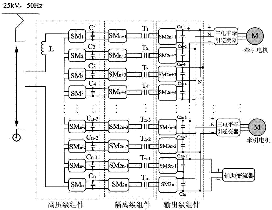
[0030] Embodiment 1: The transformer used for the three-level traction converter of the present invention is based on electronic power transformer technology; as figure 2 As shown, taking the specific application of a transformer with two traction motors as an example, the transformer includes:

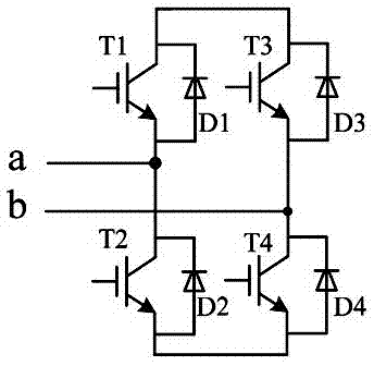
[0031] The high-voltage level components are connected to the railway traction network with an AC voltage of 25kV by connecting the reactance L, and are cascaded by cascading n-level bridge-type power sub-modules (SM1~SMn, Submodule), such as image 3 Shown is the circuit diagram of the bridge power sub-module SM. The bridge-type power sub-module adopts the H-bridge module structure, and each H-bridge is connected in parallel with capacitors (C1~Cm) of the same capacity, and the capacitors have the functions of energy storage and filtering. The H-bridge module converts the AC voltage it bears into a DC voltage across the capacitor. The H-bridge cascaded topology can not only increa...

Embodiment 2

[0034] Embodiment 2: the transformer used for the three-level traction converter of the present invention is based on electronic power transformer technology; as Figure 5 As shown, taking the specific application of a transformer with two traction motors as an example, the transformer includes:

[0035] The high-voltage level components are connected to the railway traction network with an AC voltage of 25kV by connecting the reactance L, and are cascaded by cascading n-level bridge-type power sub-modules (SM1-SMn, Submodule), such as image 3 Shown is the circuit diagram of the bridge power sub-module SM. The bridge-type power sub-module adopts the H-bridge module structure, and each H-bridge is connected in parallel with capacitors (C1-Cm) of the same capacity, and the capacitors have the functions of energy storage and filtering. The H-bridge module converts the AC voltage it bears into a DC voltage across the capacitor. The H-bridge cascaded topology can not only increa...


PUM


Abstract

The invention discloses a transformer for a three-level traction converter, comprising: a high-voltage level component connected to a traction network, and the high-voltage level component is formed by cascading n levels of the same bridge-type power sub-modules; The isolation level component includes a high-frequency modulation circuit and a high-frequency transformer. The high-frequency modulation circuit modulates the DC voltage transformed by the high-voltage level component into a high-frequency square wave voltage, which is then coupled to the other side by the high-frequency transformer and sent to the Output stage components; output stage components, including high-frequency H-bridge rectifier circuit, used to restore the high-frequency square wave coupled through the high-frequency transformer into high-quality DC voltage output, for the three-level neutral point clamp of the traction motor Bit inverter NPC and auxiliary inverter provide energy. The invention can reduce the weight of the train, reduce the volume of the train, improve the running performance of the train and the capacity of the railway, and improve the power quality of the grid.

Description

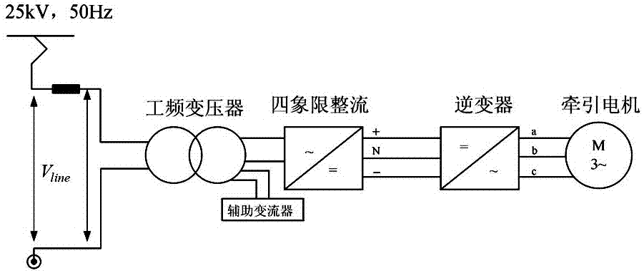
technical field [0001] The invention mainly relates to the technical field of locomotive traction, in particular to a transformer suitable for a three-level traction converter on traction transmission systems such as electric locomotives and EMUs. Background technique [0002] Such as figure 1 As shown, the power frequency transformer in the three-level traction converter of a traditional electric locomotive reduces the 25kV AC voltage to the voltage level suitable for the traction motor and other on-board electrical appliances, and the four-quadrant rectifier converts the power frequency AC voltage into DC Voltage, since the DC voltage contains 2 pulses, it is necessary to add 2 LC filter circuits to the four-quadrant output DC voltage, and then provide DC power to the inverter to drive the traction motor. That is, the secondary winding of the main transformer supplies power to the three-level rectifier, and the auxiliary winding supplies power to the auxiliary transformer...

Claims


Application Information

Patent Timeline
Patent Type & Authority Patents(China)
IPC IPC(8): H02M5/42H02M7/219H02M3/335
Inventor 张志学刘华东王奎冯江华尚敬顾春阳李飞亚罗文广陈涛严伟光
Owner CSR ZHUZHOU ELECTRIC LOCOMOTIVE RES INST
Learn More