
Highly absorbing layer system, method for producing the layer system and suitable sputtering target therefor

A technology of sputtering target and absorbing layer, which is applied in the field of sputtering target and can solve the problems of toxic Cr-Vl compounds and the like

Inactive Publication Date: 2015-09-23
MATERION ADVANCED MATERIALS GERMANY GMBH +1
View PDF6 Cites 9 Cited by
  • Summary
  • Abstract
  • Description
  • Claims
  • Application Information

AI Technical Summary

Problems solved by technology

[0008] Furthermore, the Cr-based "black matrix layers" used especially up to the 5th generation substrates have the disadvantage of the possible formation of toxic Cr-Vl compounds during wet chemical etching

Method used


Image

  • Highly absorbing layer system, method for producing the layer system and suitable sputtering target therefor
  • Highly absorbing layer system, method for producing the layer system and suitable sputtering target therefor
  • Highly absorbing layer system, method for producing the layer system and suitable sputtering target therefor

Examples


example

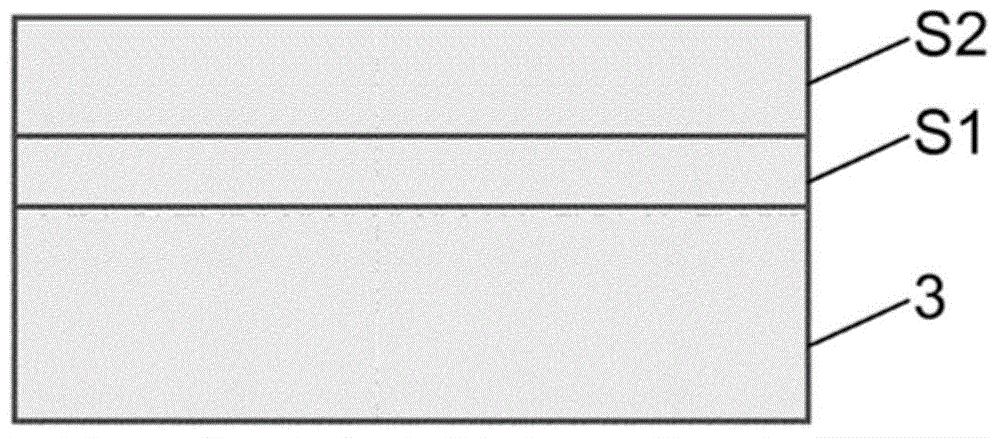
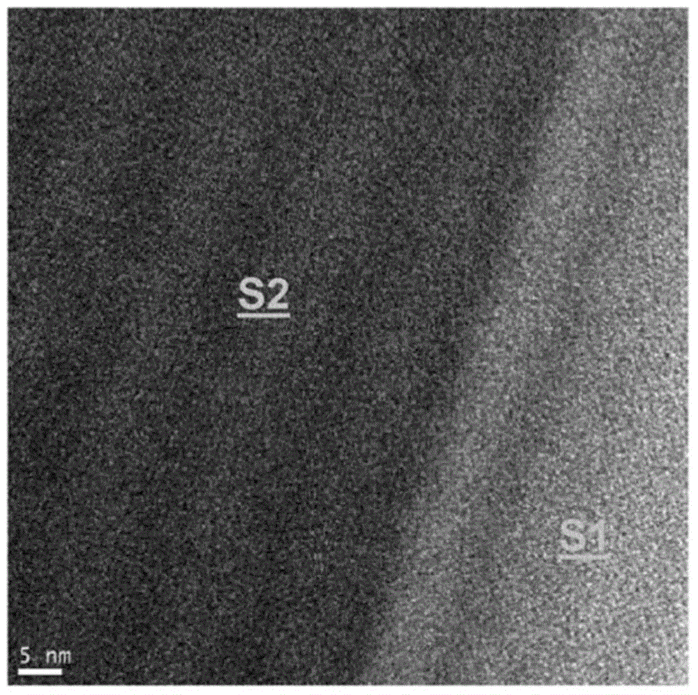
[0080] Table 1 shows the corresponding metal contents of the sputtering targets used and for Nb with Mo 2 o 5 Layer thicknesses of layers S1 and S2 of the layer system, and deposition conditions. Transmission T V The results of the measurements on the layer stack are given in Table 2 and the reflection Rv (deduction of 4% of the reflection on the front side of the uncoated glass substrate) and the Kappa absorption index at 550 nm.

[0081] Table 1 (deposition conditions)

[0082]

[0083] Table 2 (layer characteristics)

[0084]

[0085]

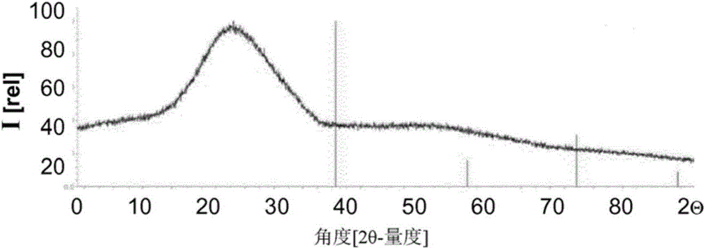
[0086] Note on the indicated weight ratios (wt%) of Mo: This indication refers to the content of Mo metal in the target material, respectively. In these layers and especially in the absorber layer S2, with a distribution of oxygen in Nb and Mo that cannot be determined in an exact manner, substoichiometric oxides Nb-Mo-O are formed x composed of an amorphous structure.

[0087] Requirements regarding visible transmission (Tv<1...


PUM

PropertyMeasurementUnit
thicknessaaaaaaaaaa
thicknessaaaaaaaaaa
thicknessaaaaaaaaaa

Abstract

The invention relates to a light absorbing layer system consisting of at least two layers, one of which is an anti-reflective layer which faces an observer and which is made from a dielectric material, and at least one other layer is an absorbing layer facing away from the observer and is made from an oxide or from an oxynitride having a sub-stoichiometric oxygen content. Said layer system has a wavelength range of between 380 - 780nm including a visual transmission Tv of less than 1% and a visual reflection Rv of less than 6% and is characterised by a kappa absorption index of at least 0.70 with a wavelength of 550 mn.

Description

technical field [0001] The invention relates to a highly absorbing layer system consisting of at least two layers, wherein one layer is an antireflection layer made of a dielectric material facing the observer and at least one other absorbing layer facing away from the observer . [0002] Furthermore, the invention relates to a method for producing said layer system, which comprises depositing an absorber layer by DC or MF sputtering of a sputtering target in an argon-containing sputtering environment, and the invention It relates to a sputtering target suitable for carrying out the method. Background technique [0003] Light-absorbing layer systems are produced, for example, by depositing successive layers by cathodic atomization (sputtering). The atoms or compounds of the solid (sputtering target) are ejected here by bombardment with energetic ions, generally noble gas ions, and into the gas phase. The atoms or molecules in the gas phase are finally deposited by condens...

Claims


Application Information

Patent Timeline
Patent Type & Authority Applications(China)
IPC IPC(8): G02B1/116G02B5/22
CPCG02B1/116G02F1/133512G02B5/22G02B5/003F24J2/487C23C14/3414Y02E10/40F24J2/4652F24S70/225F24S70/25F24S70/30G02B1/11
Inventor 马丁·施洛特阿尔伯特·卡斯特纳马库斯·舒尔特海斯詹斯·瓦格纳扎比内·施奈德-贝茨威尔玛·德瓦尔德伯恩德·西斯泽卡福尔克尔·西廷格
Owner MATERION ADVANCED MATERIALS GERMANY GMBH
Learn More