Industrial robot transmission shaft key groove machining fixture

A technology of industrial robots and drive shafts, which is applied in the direction of manufacturing tools, metal processing equipment, metal processing machinery parts, etc., can solve problems such as inconvenient clamping engineering, tolerance of parts in the same batch, inaccurate clamping reference plane, etc. Achieve the effects of reduced auxiliary processing time, low manufacturing cost, and high clamping and positioning accuracy

Inactive Publication Date: 2015-09-30
EFORT INTELLIGENT EQUIP CO LTD
View PDF14 Cites 4 Cited by
  • Summary
  • Abstract
  • Description
  • Claims
  • Application Information

AI Technical Summary

Problems solved by technology

[0002] The processing fixture of industrial robot parts will affect the processing accuracy of parts, thus affecting the overall positioning accuracy and dynamic performance of the robot
[0003] At present, in the parts processing fixtures of robots, many fixtures are ordinary and complex, which is very inconvenient in the actual clamping project, especially in the batch processing process, the key dimensions are easy to exceed the tolerance, or the same batch of parts Easy to exceed the required tolerance
For example, when machining the keyway of a robot transmission shaft, using ordinary fixtures such as a vise to hold the part can easily cause inaccurate axial and radial positioning, the surface of the part is easily clamped and damaged, and the clamping reference is not easy to locate, making tool setting and programming difficult. inconvenient
This not only increases the auxiliary time of clamping and wastes processing man-hours, but also the reference plane of each clamping is inaccurate, resulting in unqualified keyway symmetry

Method used


Image

  • Industrial robot transmission shaft key groove machining fixture
  • Industrial robot transmission shaft key groove machining fixture
  • Industrial robot transmission shaft key groove machining fixture

Examples


Embodiment Construction

[0018] In order to make the purpose, technical solutions and beneficial effects of the present invention more clear, the preferred embodiments of the present invention will be described in detail below in conjunction with the accompanying drawings, and the present invention will be further described to facilitate the understanding of technical personnel.

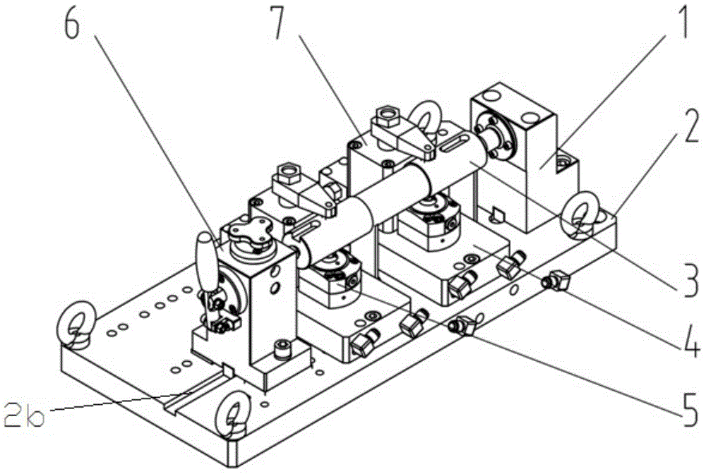
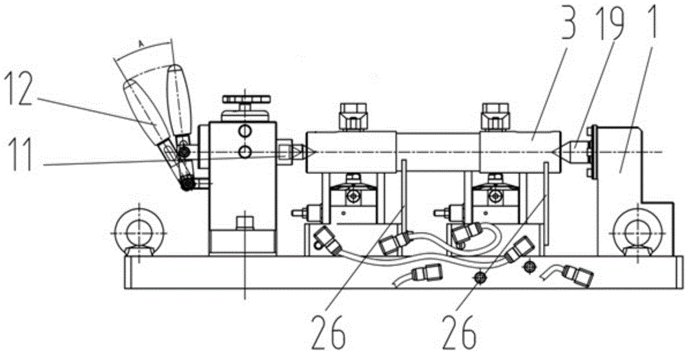
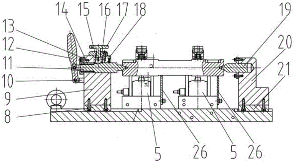
[0019] Such as Figure 1 to Figure 6 As shown, a processing fixture for the keyway of the transmission shaft of an industrial robot includes a fixture bottom plate 2, a fixed tailstock 1 is installed on the upper right end of the fixture bottom plate 2, and two oil cylinder bottom plates 4 are symmetrically installed in the middle of the upper end of the fixture bottom plate 2 , the front parts of the upper ends of the two oil cylinder base plates 4 are all equipped with top tightening cylinders 5, the upper end rear parts of the two oil cylinder base plates 4 are all equipped with compression cylinders 7, and the upper left ...


PUM


Abstract

The invention discloses an industrial robot transmission shaft key groove machining fixture. The industrial robot transmission shaft key groove machining fixture comprises a fixture base plate, the upper right end of the fixture base plate is provided with a fixed tailstock, the middle portion of the upper end of the fixture base plate is provided with two oil cylinder base plates, the upper ends of the oil cylinder base plates are provided with top-tight cylinders, the rear portions of the upper ends of the oil cylinder base plates are provided with compressing cylinders, the left portion of the upper end of the fixture base plate is provided with a top-tight tailstock, four corners of the fixture base plate are provided with hanging rings, and the right sides of the oil cylinder base plates are provided with V-shaped supports. The industrial robot transmission shaft key groove machining fixture has the advantages that the structural design is reasonable, the production and manufacture cost are low, and the clamping and positioning accuracy are high; quick clamping of a transmission shaft of an industrial robot can be achieved, the auxiliary machining time of clamping is shortened, the production efficiency is improved, and the machining cost is lowered.

Description

technical field [0001] The invention relates to the technical field of production and processing of industrial robot parts, in particular to a processing fixture for key grooves of drive shafts of industrial robots. Background technique [0002] The processing fixture of industrial robot parts will affect the processing accuracy of parts, thus affecting the overall positioning accuracy and dynamic performance of the robot. [0003] At present, in the parts processing fixtures of robots, many fixtures are ordinary and complex, which is very inconvenient in the actual clamping project, especially in the batch processing process, the key dimensions are easy to exceed the tolerance, or the same batch of parts It is easy to exceed the required tolerance. For example, when machining the keyway of a robot transmission shaft, using ordinary fixtures such as a vise to hold the part can easily cause inaccurate axial and radial positioning, the surface of the part is easily clamped an...

Claims


Application Information

Patent Timeline
Patent Type & Authority Applications(China)
IPC IPC(8): B23Q3/00
CPCB23Q3/00B23Q2703/04B23Q2703/10
Inventor 张宏强许礼进游玮曾辉肖永强赵从虎章林翟莹莹付晓玲刘阳程皓陈青
Owner EFORT INTELLIGENT EQUIP CO LTD
Why Eureka
Try Eureka