Water cooling nozzle without air pump

A technology of water cooling and air pump, which is applied in the direction of exhaust device, air quality improvement, noise reduction device, etc. It can solve the problems of nozzles and internal structures that are easy to freeze and crack, cannot realize timely pressure compensation, and shorten service life, so as to avoid frostbite, The effect of compact structure and low processing difficulty

Inactive Publication Date: 2015-09-30
SUZHOU POWERGREEN EMISSION SOLUTION SYST
View PDF4 Cites 5 Cited by
  • Summary
  • Abstract
  • Description
  • Claims
  • Application Information

AI Technical Summary

Problems solved by technology

[0004] The airless injection system injects the urea solution into the urea injection unit. The nozzle of the airless injection system is in the actual SCR loading layout. In order to reduce the pressure loss and affect the atomization, the nozzle must be installed on the exhaust pipe. Among them, due to the closeness to the exhaust pipe, its temperature will rise. Although the cooling liquid is proposed in the prior art, the heat dissipation effect is poor due to the limited heat dissipation area.
[0005] In addition, during the injection process, when the injection amount changes, the measurement accuracy will be reduced due to the influence of the pressure difference, and the timely compensation for the pressure cannot be realized; under cold conditions, the residual liquid in the metering valve will expand, and it is easy to freeze and crack Nozzle and internal structure, resulting in shortened service life

Method used


Image

  • Water cooling nozzle without air pump
  • Water cooling nozzle without air pump
  • Water cooling nozzle without air pump

Examples


Embodiment 1

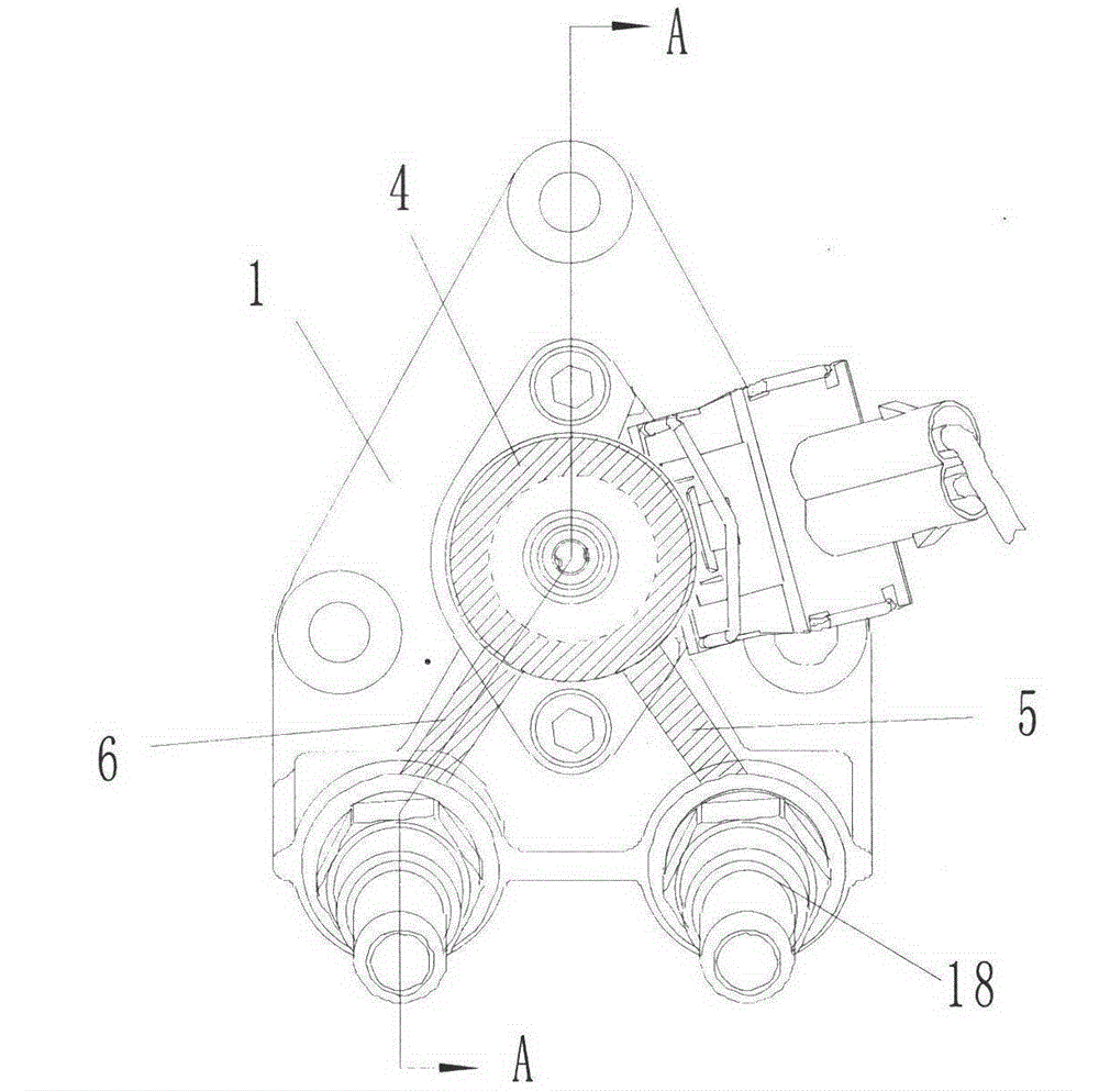
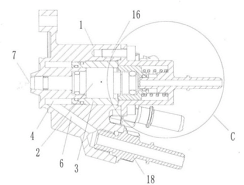
[0037] An airless pump water cooling nozzle such as figure 2 shown, combined with figure 1 , including a housing 1, a through hole is opened in the center of the housing 1, a metering valve 2 is placed in the through hole, and one end of the through hole is connected with the nozzle of the metering valve 2 to form an injection port 19.

[0038]A cooling chamber 4 and a blocking cover 3 are provided on the housing 1, and the blocking cover 3 and the cooling chamber 4 surround the periphery of the metering valve 2, specifically, openings in the housing 1 An annular channel, the channel is located at the periphery of the metering valve 2, and the plugging cover 3 is embedded in the channel, and the blocking cover 3 can seal the upper half of the channel, so that The lower half of the passage forms the cooling chamber 4 of the closed structure, referring to figure 1 , the housing 1 is provided with a water inlet passage 5 and a water outlet passage 6, and the water inlet passa...

Embodiment 2

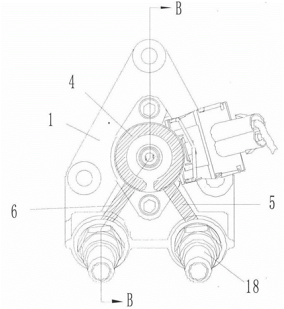
[0049] A water-cooled nozzle without an air pump, including a housing 1, referring to Figure 4 , and combined with image 3 , a metering valve 2 is installed in the housing 1, a cooling chamber 4 and a plugging cover 3 are arranged on the housing 1, the cooling chamber 4 is formed by a semi-circular structure channel, and the plugging cover 3 is fixed on The bottom end of the housing 1, its top surface is formed at the bottom of the cooling chamber 4, the fixing method of the blocking cover 3 and the housing 1 can be fixed by welding or limit pin 17, the main The purpose is to play a positioning role and a sealing effect.

[0050] A liquid inlet joint 18 is installed on the housing 1, combined with Figure 6 , the head of the metering valve 2 is covered with a telescopic sleeve 8, the bottom of the telescopic sleeve 8 and the bottom of the liquid inlet connecting pipe 18 are fixed to the housing 1, and the rest are the same as in Embodiment 1. The advantage of the embodime...


PUM


Abstract

The invention discloses a water cooling nozzle without an air pump and relates to the technical field of automobile exhaust processing. The water cooling nozzle comprises a shell, a metering valve is arranged in the shell, and a cooling room defined by a blocking cover is arranged on the periphery of the metering valve. The cooling room can achieve efficient cooling on the metering valve. A telescopic sleeve is arranged on the head of the metering valve, the metering valve is connected with a liquid inlet connecting pipe, an elastic part is arranged between the telescopic sleeve and the liquid inlet connecting pipe, and a buffering cavity is formed between the telescopic sleeve and the metering valve. The effects of stabilizing pressure and storing energy can be achieved through the buffering cavity, the metering precision is ensured, residual liquid in the metering valve can be removed in time through the elastic part, and therefore the metering valve is prevented from being frozen to be damaged.

Description

technical field [0001] The present invention relates to the technical field of SCR post-processing system for automobile exhaust treatment, in particular to an injection unit used on an airless urea metering pump, which includes metering valves, cooling water jackets, buffer devices and other functional parts, and has metering valves for high-temperature heat dissipation , Energy storage voltage stabilization and freezing expansion protection function. Background technique [0002] With the continuous improvement of people's requirements for air environment quality, my country has begun to implement strict control on vehicle engine emissions, and has formulated relatively strict standards, which have quite high requirements for exhaust gas treatment technology. [0003] At present, SCR technology is mainly used in the world for treatment. The technical principle is that under the condition of rich oxygen in the exhaust gas, a reducing agent is injected into the exhaust gas, ...

Claims


Application Information

Patent Timeline
Patent Type & Authority Applications(China)
IPC IPC(8): F01N3/28F01N13/14
CPCY02A50/20
Inventor 郝庆军李占贵
Owner SUZHOU POWERGREEN EMISSION SOLUTION SYST
Why Eureka
Try Eureka