Lens wavefront aberration measurement method based on inverse hartmann principle

A technology of wavefront aberration and measurement method, applied in measurement device, measurement optics, optical radiation measurement and other directions, can solve problems such as focus confusion, and achieve the effects of simple device, high measurement accuracy and high spatial resolution

Inactive Publication Date: 2015-09-30
SICHUAN UNIV
View PDF4 Cites 21 Cited by
  • Summary
  • Abstract
  • Description
  • Claims
  • Application Information

AI Technical Summary

Problems solved by technology

In addition, in order to avoid focus confusion, it is not suitable t

Method used


Image

  • Lens wavefront aberration measurement method based on inverse hartmann principle
  • Lens wavefront aberration measurement method based on inverse hartmann principle
  • Lens wavefront aberration measurement method based on inverse hartmann principle

Examples


Embodiment Construction

[0020] The following is attached Figures 1 to 3 Embodiments of the present invention will be described.

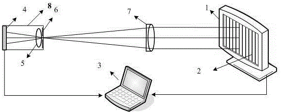
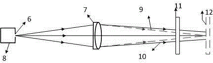
[0021] A lens wavefront aberration measurement method based on the inverse Hartmann principle, the system design is as follows figure 1 As shown, it mainly consists of an LCD display 1, a digital CCD camera 8, and a computer 3. The CCD camera 8 is composed of a CCD detection plane 4, a camera lens system 5 and an external pinhole 6, wherein the pinhole 6 is installed near the outside of the CCD camera lens to eliminate the influence of pupil aberration on the system. Its system measurement principle is as follows figure 2 As shown, if the light propagation direction is viewed according to Hartmann's principle, the pinhole 6 in the system is regarded as a point light source, and the light 10 reaches a certain position on the LCD display screen 11 after passing through the measured lens 7 . There is a deviation between this position and the ideal light 9, and this devia...


PUM


Abstract

The invention provides a lens wavefront aberration measurement method. A group of horizontal and vertical sine phase shifting fringe patterns 2 is generated by an LCD (Liquid Crystal Display) 1; a CCD (Charge Coupled Device) camera 8 is composed of a focal plane 4, a camera lens 5 and an external pinhole 6, and the LCD 1, the camera 8 and a to-be-measured lens 7 are collimated and calibrated, so as to obtain spatial coordinates of the LCD 1, the camera 8 and the to-be-measured lens 7; the phase shifting fringe patterns 2 which are deflected by the to-be-measured lens 7 and are displayed by the LCD 1 are shot, and then a group of horizontal and vertical phase shifting fringe patterns 2 are shot as a reference after the to-be-measured lens 7 is removed; finally, the shot phase shifting fringe patterns 2 are combined with a computer 3 for phase unwrapping, a slope is calculated, a wavefront is restored, and wavefront aberration is analyzed according to the wavefront of a restored transmission optical system.

Description

technical field [0001] The invention relates to a method for measuring lens wavefront aberration based on the inverse Hartmann principle. Background technique [0002] The detection of the surface shape and wavefront of optical components is essential in the processing and assembly of optical components. It is usually divided into direct measurement of surface shape and slope measurement, which correspond to interferometer measurement and light deflection measurement respectively. Since the surface shape parameter only expresses the physical properties, it can guide the final ideal surface shape, but it cannot intuitively express the influence of light deflection on the optical performance of the system. In addition, interferometer measurement requires manual and precise calibration, and the requirements for supporting equipment are strict and demanding. When measuring the wavefront, it is easily affected by environmental factors such as air disturbances, and has high requir...

Claims


Application Information

Patent Timeline
IPC IPC(8): G01J9/00
Inventor 李大海李萌阳洪之涵鄂可伟
Owner SICHUAN UNIV
Why Eureka
Try Eureka